Westinghouse MT80 ARM20 Installation Instructions - Page 8
Caution
 |
View all Westinghouse MT80 ARM20 manuals
Add to My Manuals
Save this manual to your list of manuals |
Page 8 highlights
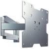
3 Adjust tension knob on side of mount shown in figure 3 to desired tension to balance your screen size and weight. Push or pull from top or bottom of screen to adjust tilt as shown. The tilt can be adjusted to a maximum of 15° forward or 5° backward. CAUTION • Do not tighten screws with excessive force. Overtightening can cause damage to mount. Tighten screws to 40 in. • lb (4.5 N.M.) maximum torque. CAUTION • Be careful not to pinch fingers when opening and closing mount from the wall. TENSION KNOB fig. 3 Note: Make sure cords have enough slack to allow full movement of the arm. 4 Route cords inside arm slots of wall mount (A) as shown in figure 4.1. Optional: Run power cord through one side of mount and signal cable(s) through other side in order to avoid interference with the signal. Lock cords into place by sliding cord covers (I) onto mount as shown in figure 4.2. Screen may have to be moved for better access for sliding on the cord covers. I fig. 4.1 A 8 of 10 fig. 4.2 ISSUED: 01-17-06 SHEET #: 202-9094-1
-
 1
1 -
2
-
 3
3 -
 4
4 -
 5
5 -
 6
6 -
 7
7 -
 8
8 -
 9
9 -
 10
10
 |
 |
