Whirlpool G9CE3675XB Dimension Guide - Page 1
Whirlpool G9CE3675XB Manual
 |
View all Whirlpool G9CE3675XB manuals
Add to My Manuals
Save this manual to your list of manuals |
Page 1 highlights
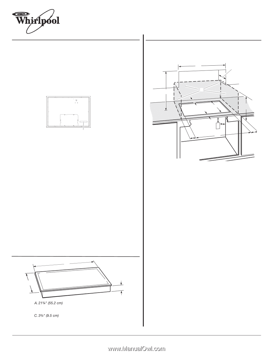
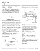
® Electric Built-in Cooktop PRODUCT MODEL NUMBERS G7CE3034X G7CE3055X G7CE3635X G7CE3655X G9CE3065X G9CE3074X G9CE3675X W5CE3024X Before You Make the Electrical Connection: To properly install your cooktop, you must determine the type of electrical connection you will be using and follow the instructions provided for it here. q A 3-wire or 4-wire, single phase, 120/240 volt, 60-Hz., AC only electrical supply is required on a separate, 40-amp circuit fused on both sides of the line. The model/serial number rating plate is located on the metal cabinet underneath the cooktop. See the following illustration. CABINET OPENING DIMENSIONS IMPORTANT: If installing a range hood or microwave hood combination above the cooktop, follow the range hood or microwave hood combination installation instructions for dimensional clearances above the cooktop surface. A D C B L F G E A A. Model/serial number plate q The cooktop is rated 120/240 volt. Most models have a neutral (white) wire. Model W5CE3024 does not have a neutral (white) wire. q The cooktop should be connected directly to the junction box through flexible, armored or nonmetallic sheathed, copper cable. The flexible, armored cable extending from the fuse box or circuit breaker box should be connected directly to the junction box. q Locate the junction box to allow as much slack as possible between the junction box and the cooktop so that the cooktop can be moved if servicing becomes necessary in the future. q Do not cut the conduit. Use the length of conduit provided. q A UL listed or CSA approved conduit connector must be provided at each end of the power supply cable (at the cooktop and at the junction box). A listed conduit connector is already provided at the cooktop. q If the house has aluminum wiring, follow the procedure below: 1. Connect a section of solid copper wire to the pigtail leads. 2. Connect the aluminum wiring to the added section of copper wire using special connectors and/or tools designed and UL listed for joining copper to aluminum. Follow the electrical connector manufacturer's recommended procedure. Aluminum/copper connection must conform with local codes and industry accepted wiring practices. PRODUCT DIMENSIONS B A C B. 30" (76.2 cm) models - 30 78.4 cm) 36" (91.4 cm) models - 36 92.3 cm) H I K J A. 30" (76.2 cm) on 30" models; 36" (91.4 cm) on 36" models B. Combustible area above countertop (shown by dashed box above) C. 30" (76.2 cm) minimum clearance between top of cooktop platform and bottom of uncovered wood or metal cabinet (24" [61 cm] minimum clearance if bottom of wood or metal cabinet is covered by not less than ¹⁄₄" [0.6 cm] flame retardant millboard covered with not less than No. 28 MSG sheet steel, 0.015" [0.04 cm] stainless steel, or 0.024" [0.06 cm] aluminum or 0.020" [0.05 cm] copper) D. 13" (33 cm) recommended upper cabinet depth E. 2" (5.1 cm) F. 20 52.0 +/- 0.16 cm) G. 18" (45.7 cm) minimum clearance from upper cabinet to countertop within minimum horizontal clearances to cooktop H. Junction box or outlet: 7" (17.8 cm) minimum from top of countertop I. Junction box or outlet: 9" (23.0 cm) maximum from right side of cabinet J. 29 74.9 +/- 0.16 cm) on 30" (76.2 cm) models 35 90.2 cm + 0.16 cm/- 2.38 cm) on 36" (91.4 cm) models K. 1" (2.5 cm) minimum distance to nearest left and right side combustible surface above cooktop L. 1" (2.5 cm) minimum clearance between back wall and countertop NOTES: After making the countertop cutout, some installations may require notching down the base cabinet side walls to clear the cooktop base. To avoid this modification, use a base cabinet with sidewalls wider than the cutout. If cabinet has a drawer, a 5¹⁄₂" (14.0 cm) depth clearance from the top of the countertop to the top of the drawer (or other obstruction) in base cabinet is required. Because Whirlpool Corporation policy includes a continuous commitment to improve Dimensions are for planning purposes only. For complete details, see Installation our products, we reserve the right to change materials and specifications without notice. Instructions packed with product. Specifications subject to change without notice. Ref. W10346695A 2/28/11
-
 1
1
 |
 |