Whirlpool GGE390LXB Installation Instructions - Page 10
wire connection: Power Supply Cord, wire connection: Power Supply Cord
 |
View all Whirlpool GGE390LXB manuals
Add to My Manuals
Save this manual to your list of manuals |
Page 10 highlights
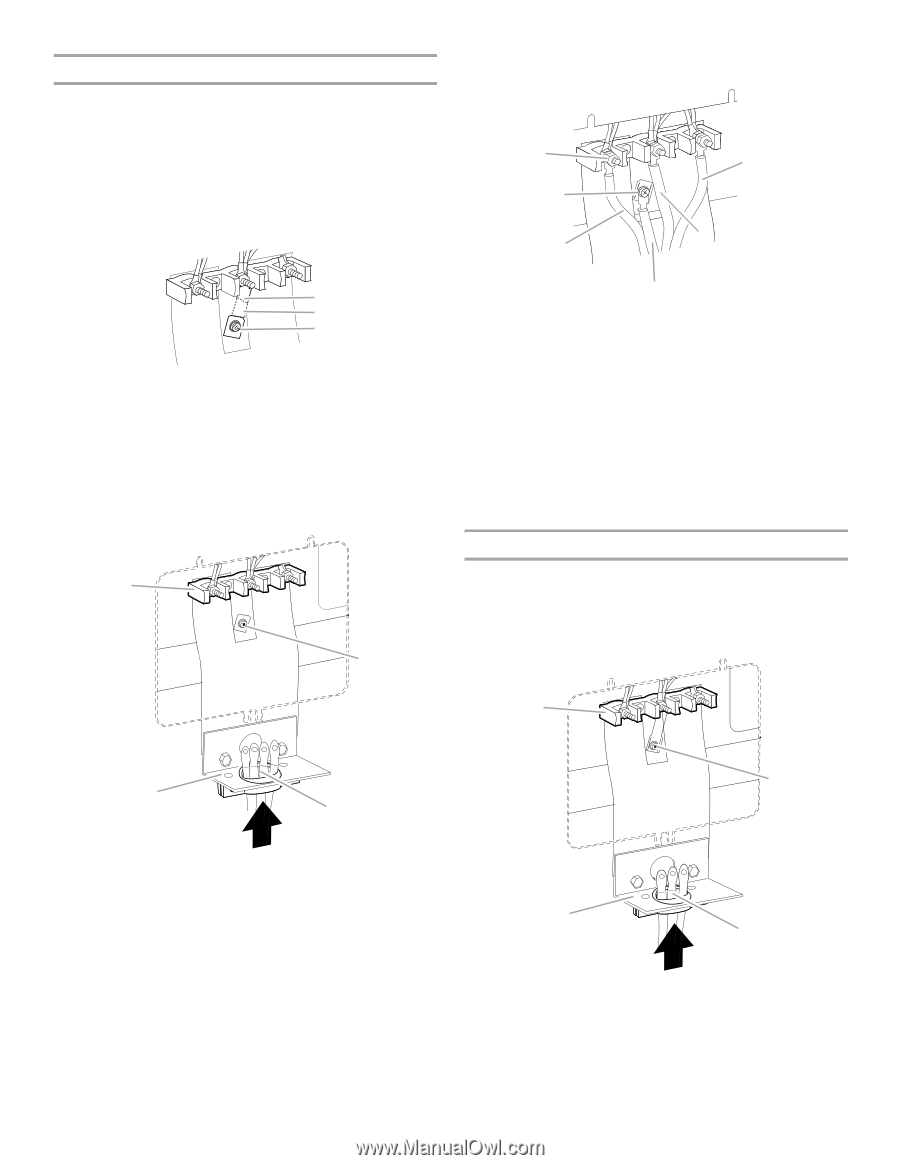
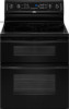
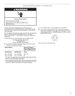
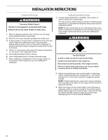
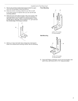
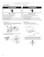
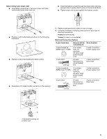
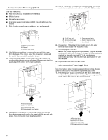
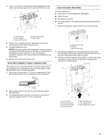
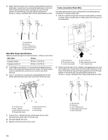
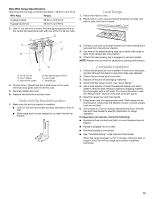
4-wire connection: Power Supply Cord Use this method for: ■ New branch-circuit installations (1996 NEC) ■ Mobile homes ■ Recreational vehicles ■ In an area where local codes prohibit grounding through the neutral 1. Part of metal ground strap must be cut out and removed. 5. Use ³⁄₈" nut driver to connect the neutral (white) wire to the center terminal block post with one of the 10-32 hex nuts. A B C F E A B C A. Metal ground strap B. Discard C. Ground-link screw 2. Use Phillips screwdriver to remove the ground-link screw from the back of the range. Save the ground-link screw and the end of the ground link under the screw. 3. Feed the power supply cord through the strain relief in the cord/conduit plate on bottom of range. Allow enough slack to easily attach the wiring to the terminal block. A B D A. 10-32 hex nut B. Ground-link screw C. Line 1 (black) D. Green ground wire E. Neutral (center) wire F. Line 2 (red) 6. Connect line 1 (black) and line 2 (red) wires to the outer terminal block posts with 10-32 hex nuts. 7. Securely tighten hex nuts. NOTE: For power supply cord replacement, only use a power cord rated at 250 volts minimum, 40 amps or 50 amps that is marked for use with nominal 1³⁄₈" (3.5 cm) diameter connection opening, with ring terminals and marked for use with ranges. 8. Replace terminal block access cover. 3-wire connection: Power Supply Cord Use this method only if local codes permit connecting chassis ground conductor to neutral wire of power supply cord. 1. Feed the power supply cord through the strain relief in the cord/conduit plate on bottom of range. Allow enough slack to easily attach the wiring to the terminal block. A C D A. Terminal block B. Ground-link screw C. Cord/conduit plate D. Power supply cord wires 4. Use Phillips screwdriver to connect the green ground wire from the power supply cord to the range with the ground-link screw. The ground wire must be attached first. B C D A. Terminal block B. Ground-link screw C. Cord/conduit plate D. Power supply cord wires 10
-
 1
1 -
2
-
3
-
4
-
 5
5 -
 6
6 -
 7
7 -
 8
8 -
 9
9 -
 10
10 -
 11
11 -
 12
12 -
 13
13 -
 14
14 -
 15
15 -
16
-
17
-
18
-
19
-
20
-
21
-
22
-
23
-
24
 |
 |