Whirlpool MH1170XS Installation Instructions
Whirlpool MH1170XS Manual
 |
View all Whirlpool MH1170XS manuals
Add to My Manuals
Save this manual to your list of manuals |
Whirlpool MH1170XS manual content summary:
- Whirlpool MH1170XS | Installation Instructions - Page 1
MICROWAVE HOOD COMBINATION INSTALLATION INSTRUCTIONS This product is suitable for use above electric or gas cooking products up to 36" (91.4 cm) wide. These installation instructions cover different models. The appearance of your particular model may differ slightly from the illustration in these - Whirlpool MH1170XS | Installation Instructions - Page 2
REQUIREMENTS Tools and Parts Tools Needed Gather the required tools and parts before starting installation. Read and follow the instructions provided with any tools listed here. Location Requirements Check the opening where the microwave oven will be installed. The location must provide - Whirlpool MH1170XS | Installation Instructions - Page 3
Installation Dimensions NOTE: The grounded 3 prong outlet must be inside the upper cabinet. See "Electrical Requirements" min. Do not use an extension cord. Failure to follow these instructions can result in death, fire, or electrical shock. Observe all governing codes and ordinances. Required: - Whirlpool MH1170XS | Installation Instructions - Page 4
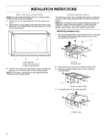
strips of tape that attach it to the back of the microwave oven, and set the mounting plate aside. Rotate Blower Motor The microwave oven is set for ventless (recirculating) installation. For wall or roof venting, changes must be made to the venting system. NOTE: Skip this section if you are using - Whirlpool MH1170XS | Installation Instructions - Page 5
face the back of microwave oven, and lower it back into the microwave oven. 1. 2. 3. 4. 5. Roof Venting Installation Only Repeat Step 1 from "Wall Venting Installation Only." Repeat Step 2 from "Wall Venting Installation Only." Repeat Step 3 from "Wall Venting Installation Only." Repeat Step 4 from - Whirlpool MH1170XS | Installation Instructions - Page 6
centerline (see "Mark Rear Wall" section), only recirculation or roof venting installation can be done. One Wall Stud at Two Corner Holes Figure 3 plate) B. Cabinet opening vertical centerline C. Wall stud centerlines D. Holes for lag screws E. Support tabs F. Mounting plate center markers 6 - Whirlpool MH1170XS | Installation Instructions - Page 7
, find and clearly mark the vertical centerline of the opening. Wall Venting Installation Only Centerline Upper cabinet bottom ³⁄₈" (1 cm) 4" (10.2 cm) A 6" (15.2 cm) 6" (15.2 cm) A. Centerline 2. With the support tabs facing forward (see illustrations in "Possible Wall Stud Configurations" in - Whirlpool MH1170XS | Installation Instructions - Page 8
support tabs of the mounting plate facing forward, insert 1/4-20 x 3" round-head bolts through the 2 corner holes that fit over the two 3/4" (19 mm) holes drilled in Step 2 of "Installation in the top of the microwave oven. NOTE: If the use as guides. 4. Make sure the 10" (25.4 cm) dimension from the - Whirlpool MH1170XS | Installation Instructions - Page 9
10 mm) holes. 2. Make sure the microwave oven door is closed and taped shut. For Roof Venting Installation Only 7. Cut 3/4" (19 mm) installation. A B A. Mounting plate B. Support tabs D A. Back of microwave oven B. Damper assembly C. Damper blade D. Sheet metal screws 4. With front of microwave - Whirlpool MH1170XS | Installation Instructions - Page 10
off of mounting plate, and set aside on a protected surface. 8. Loosen mounting plate screws. Adjust mounting plate and retighten screws. 9. Repeat steps 3-6. 10. With the microwave oven centered, and with at least one person holding it in place, insert bolts through upper cabinet into - Whirlpool MH1170XS | Installation Instructions - Page 11
VENTING DESIGN SPECIFICATIONS This section is intended for architectural designer and builder/ contractor reference only. NOTES: - Whirlpool MH1170XS | Installation Instructions - Page 12
on the model and serial number plate, which is located behind the microwave oven door on the front frame of the microwave oven. If you need additional assistance, call us at our toll free number listed in the Use and Care Guide, or visit us on the Web. Replacement Parts If any of the installation
-
 1
1 -
 2
2 -
 3
3 -
 4
4 -
 5
5 -
 6
6 -
 7
7 -
8
-
9
-
10
-
11
-
12
 |
 |

MICROWAVE HOOD COMBINATION
INSTALLATION INSTRUCTIONS
MICROWAVE HOOD COMBINATION SAFETY
This product is suitable for use above electric or gas cooking products up to 36" (91.4 cm) wide.
These installation instructions cover different models. The appearance of your particular model may differ slightly from the
illustration in these installation instructions.
NOTES:
■
Proper installation is the responsibility of the installer.
■
Product failure due to improper installation is not covered under the warranty.
Table of Contents
MICROWAVE HOOD COMBINATION SAFETY
..............................
1
INSTALLATION REQUIREMENTS
...................................................
2
Tools and Parts
...............................................................................
2
Location Requirements
...................................................................
2
Product Dimensions
.......................................................................
3
Electrical Requirements
..................................................................
3
INSTALLATION INSTRUCTIONS
.....................................................
4
Remove Mounting Plate
.................................................................
4
Rotate Blower Motor
.......................................................................
4
Locate Wall Stud(s)
.........................................................................
6
Mark Rear Wall
................................................................................
7
Drill Holes in Rear Wall
....................................................................
7
Attach Mounting Plate to Wall
........................................................
8
Prepare Upper Cabinet
...................................................................
8
Install Damper Assembly
................................................................
9
Install the Microwave Oven
............................................................
9
Complete Installation
...................................................................
10
VENTING DESIGN SPECIFICATIONS
...........................................
11
ASSISTANCE
..................................................................................
12
Replacement Parts
......................................................................
12
Accessories
..................................................................................
12
IMPORTANT:
Read Installation Instructions thoroughly before beginning installation. Save Installation Instructions for local house
inspector’s use.
8206555
You can be killed or seriously injured if you don't immediately
You
can be killed or seriously injured if you don't follow
All safety messages will tell you what the potential hazard is, tell you how to reduce the chance of injury, and tell you what can
happen if the instructions are not followed.
Your safety and the safety of others are very important.
We have provided many important safety messages in this manual and on your appliance. Always read and obey all safety
messages.
This is the safety alert symbol.
This symbol alerts you to potential hazards that can kill or hurt you and others.
All safety messages will follow the safety alert symbol and either the word “DANGER” or “WARNING.”
These words mean:
follow instructions.
instructions.
DANGER
WARNING