Whirlpool UXL6036YSS Installation Guide - Page 9
Install Hood Liner Internal Blower Motor, Single Blower Motor Assembly, Dual Blower Motor Assembly
 |
View all Whirlpool UXL6036YSS manuals
Add to My Manuals
Save this manual to your list of manuals |
Page 9 highlights
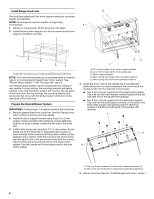
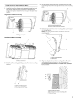
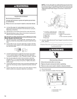
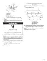
Install Hood Liner Internal Blower Motor 1. Install the hood liner blower motor assembly inside the hood liner canopy with the wiring connection to the left for the single motor system and to the front or top for the dual motor system. Single Blower Motor Assembly 3. Run the power supply wires and connector from the range hood through the hole in the right end of the motor mounting plate. A A A. Wiring connection Dual Blower Motor Assembly A B A. Motor mounting plate hole B. Power supply wires and connector 4. Push the right end of the motor mounting plate up and snap it into the spring tab. NOTE: The spring tab should be outside the slot in the mounting plate. A B A. Wiring connection 2. Slide the left mounting plate flange under the motor mounting bracket. A. Motor mounting plate B. Spring clip 5. Align mounting holes in motor mounting plate with motor mounting clip nuts and install 6 x 16 mm screws and 6.4 mm lock washers (quantity 2 for single motor; quantity 5 for dual motor). AB A. Motor mounting bracket B. Mounting plate left flange C B A A. Screw with lock washer B. Mounting hole in motor mounting plate C. Clip nut (6 mm) 9
-
 1
1 -
2
-
3
-
 4
4 -
 5
5 -
 6
6 -
 7
7 -
 8
8 -
 9
9 -
 10
10 -
 11
11 -
 12
12 -
 13
13 -
 14
14 -
15
-
16
-
17
-
18
-
19
-
20
-
21
-
22
-
23
-
24
-
25
-
26
-
27
-
28
-
29
-
30
-
31
-
32
-
33
-
34
-
35
-
36
 |
 |
