Whirlpool UXT4230AYS Use & Care Guide - Page 13
Wiring Diagram
 |
View all Whirlpool UXT4230AYS manuals
Add to My Manuals
Save this manual to your list of manuals |
Page 13 highlights
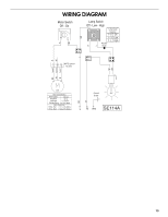
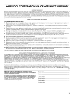
W BK BK BK W R Y WIRING DIAGRAM R Motor Switch Off - On BK Lamp Switch Off - Low - High 1 2 Lamp Switch Operation 1 - 2 Off L 3 1 - 3 Low 1 - L High Rectifier Diode NOTE: Speed 1 not used W R Speed 1 W Common Speed 2 R BK C25 Motor Characteristics Power Supply 120 VAC Frequency 60 Hz Amperage 1.2 ±10% A Wattage Rating 73 ±10% Watts Motor Resistance White - Red 17.1 ±10% Ohms White - Black 13.6 ±10% Ohms Ground Screw L N GND SE114A 13
-
 1
1 -
2
-
3
-
4
-
5
-
6
-
7
-
 8
8 -
 9
9 -
 10
10 -
 11
11 -
 12
12 -
 13
13 -
 14
14 -
 15
15 -
 16
16 -
 17
17 -
 18
18 -
19
-
20
-
21
-
22
-
23
-
24
-
25
-
26
-
27
-
28
-
29
-
30
-
31
-
32
 |
 |

13
WIRING DIAGRAM
1.2 ±10% A
73 ±10% Watts
17.1 ±10% Ohms
13.6 ±10% Ohms
Motor Characteristics
Power Supply
120 VAC
Frequency
60 Hz
Amperage
Wattage Rating
Motor Resistance
White - Red
White - Black
Lamp Switch
Off - Low - High
Motor Switch
Off - On
Lamp Switch
Operation
1 - 3
Low
1 - 2
Off
1 - L
High
Ground
Screw
GND
L
N
BK
W
R
Speed 2
Common
Speed 1
R
W
NOTE: Speed 1
not used
R
BK
BK
R
BK
W
BK
W
Y
Rectifier
Diode