Whirlpool UXT5230AYW Use & Care Guide - Page 10
Power Supply Cable Installation
 |
View all Whirlpool UXT5230AYW manuals
Add to My Manuals
Save this manual to your list of manuals |
Page 10 highlights
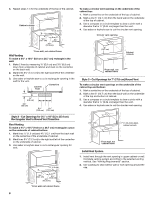
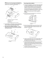
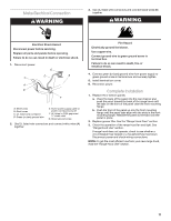
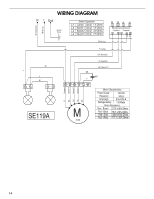
NOTE: The 7" (17.8 cm) round vent mounting plate and 3¹⁄₄" x 10" (8.3 x 25.4 cm) rectangular vent damper can be installed up to 1" (2.5 cm) on either side of the hood center to accommodate off-center ductwork. B A C D E Power Supply Cable Installation 1. For direct wire installations, run the home power supply cable according to the National Electric Code or CSA standards and local codes and ordinances. There must be enough wiring from the fused disconnect (or circuit breaker) box to make the connection in the hood electrical terminal box. For optional power supply cord kit installations, follow the instructions in the "Make Electrical Connection" section. See the "Accessories" section for information on ordering. NOTE: Do not reconnect power until the installation is complete. 2. Remove the screw from the terminal box cover. Remove terminal box cover and set aside. C B A. Vertical vent connector with damper B. 3.5 x 5 mm screws C. Hinge pin D. Vent knockouts E. Horizontal vent connector with damper ■ If a vent damper is installed with a wall cap with damper, check that they do not interfere with each other. Remove the vent connector damper flap if they interfere. ■ Non-vented (recirculating) installations - No vent attachments. Removal of the recirculation cover plate is required. Remove the two screws from the recirculation cover plate and remove. A A B A. Terminal box cover B. Screw 3. Remove the power supply knockout from the top or rear of the vent hood (depending on the incoming location of your home power supply cable) and install a UL listed or CSA approved ¹⁄₂" strain relief. A B A. Recirculation cover plate B. Screws A. Power supply knockout 4. Using 2 or more people, lift the hood into final position. Feed enough electrical wire through the ½" UL listed or CSA approved strain relief to make connections in the terminal box. Tighten the strain relief screws. 5. Position the range hood so that the large end of the keyhole slots are over the mounting screws. Then push the hood toward the wall so that the screws are in the neck of the slots. Tighten the mounting screws, making sure the screws are in the narrow neck of slots. 6. Connect ventwork to hood. Seal joints with vent clamps or duct tape to make secure and airtight. 7. Check that back draft dampers work properly. 10
-
 1
1 -
2
-
3
-
4
-
 5
5 -
 6
6 -
 7
7 -
 8
8 -
 9
9 -
 10
10 -
 11
11 -
 12
12 -
 13
13 -
 14
14 -
 15
15 -
16
-
17
-
18
-
19
-
20
-
21
-
22
-
23
-
24
-
25
-
26
-
27
-
28
-
29
-
30
-
31
-
32
 |
 |
