Whirlpool UXT5230BDS Installation Guide - Page 4
Venting System - parts
 |
View all Whirlpool UXT5230BDS manuals
Add to My Manuals
Save this manual to your list of manuals |
Page 4 highlights
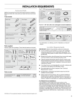
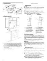
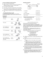
Product Dimensions 2" (5.1 cm) 6 16.7 cm) or 9 24.4 cm) 4 12.5 cm) 1" (2.5 cm) 1" (2.5 cm) 9" (22.9 cm) 29 76.0 cm) or 35 91.0 cm) 1¹⁄₂" (3.8 cm) 18⁵⁄₈" (47.3 cm) Installation Clearances Venting System Venting Methods NOTES: ■ Flexible vent is not recommended. Flexible vent creates both back pressure and air turbulence that greatly reduce performance. ■ The vent system is optional for this model. Vent system can terminate either through the roof or wall. Use 3¹⁄₄" x 10" (8.3 x 25.4 cm) rectangular with a maximum vent length of 35 ft (10.7 m) or 7" (17.8 cm) or larger round vent with a maximum length of 50 ft (15.2 m) for vent system. Top Venting Wall Venting B A A B C A D B E A. 18" (45.7 cm) minimum distance from electric cooking surface. 24" (61.0 cm) minimum distance from gas cooking surface. 30" (76.2 cm) suggested maximum above the cooking surface. B. 18" (45.7 cm) minimum clearance - upper cabinet to countertop. C. 30" (76.2 cm) minimum cabinet opening width for 30" (76.2 cm) models and 36" (91.4 cm) minimum cabinet width for 36" (91.4 cm) models. D. 12" (30.5 cm) cabinet depth. E. 36" (91.4 cm) base cabinet height. 4 A. 7" (17.8 cm) round vent through roof (purchased separately). 3¹⁄₄" x 10" (8.3 x 25.4 cm) rectangular vent through the roof (purchased separately). B. Roof cap with damper (purchased separately) A. 7" (17.8 cm) round vent out the top and through the wall (purchased separately). 3¹⁄₄" x 10" (8.3 x 25.4 cm) rectangular vent through the wall or out the top (purchased separately). B. Wall cap with damper (purchased separately) Cold Weather Installations An additional back draft damper should be installed to minimize backward cold air flow and a thermal break should be installed to minimize conduction of outside temperatures as part of the vent system. The damper should be on the cold air side of the thermal break. The break should be as close as possible to where the vent system enters the heated portion of the house. Makeup Air Local building codes may require the use of makeup air systems when using ventilation systems greater than specified CFM of air movement. The specified CFM varies from locale to locale. Consult your HVAC professional for specific requirements in your area. Venting Requirements ■ Vent system must terminate to the outdoors, except for non- vented (recirculating) installations. ■ Do not terminate the vent system in an attic or other enclosed area. ■ Do not use a 4" (10.2 cm) laundry-type wall cap. ■ Use 7" (17.8 cm) round metal vent or 3¹⁄₄" x 10" (8.3 x 25.4 cm) rectangular metal vent, depending on your installation requirement. Rigid metal vent is recommended. Plastic or metal foil vent is not recommended. ■ The length of vent system and number of elbows should be kept to a minimum to provide efficient performance.
-
 1
1 -
 2
2 -
 3
3 -
 4
4 -
 5
5 -
 6
6 -
 7
7 -
 8
8 -
 9
9 -
 10
10 -
11
-
12
-
13
-
14
-
15
-
16
-
17
-
18
-
19
-
20
-
21
-
22
-
23
-
24
-
25
-
26
-
27
-
28
-
29
-
30
 |
 |
