Whirlpool WCG55US6HS Instruction Sheet - Page 7
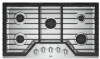
Burner locations - model
 |
View all Whirlpool WCG55US6HS manuals
Add to My Manuals
Save this manual to your list of manuals |
Page 7 highlights
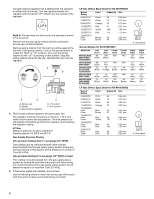
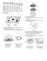
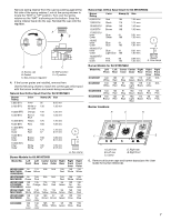
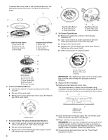
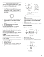
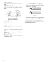
Remove spring retainer from the cap by pushing against the flat side of the spring retainer. Look at the spring retainer to locate the "NAT" or "LP" position. Turn over the spring retainer so the "NAT" is showing on the bottom. Snap the spring retainer back into the cap. Reinstall the cap onto the regulator. A B E D C A. Access cap B. Gasket C. Gas pressure regulator D. NAT position E. LP position 4. If the burner grates are installed, remove them. Use the following charts to match the correct gas orifice spud with the burner location and model being converted. Natural Gas Orifice Spud Chart for Kit W10676661 Burner Rating Color Stamp (A) Size 5,000 BTU Green 95 0.95 mm 9,100 BTU White or 130 no color 1.30 mm 10,000 BTU Orange 135 1.35 mm 12,00 BTU Red or 150 Blue 1.50 mm 15,000 BTU Yellow 175 1.75 mm 18,00 BTU Pink 189 1.89 mm 17,000 BTU Inner Red 175 Outer Red 57 1.75 mm 0.57 mm 18,00 BTU Inner Brown 180 1.80 mm A Outer Brown 57 0.57 mm 19,000 BTU Inner White 185 Outer White 57 1.85 mm 0.57 mm A. Size stamp Burner Models for Kit W10676661 Model No. Left Left Center Center Right Front Rear Inner Outer Rear WCG51US0D 95 MGC7430D Green ICS500DS00 WCG75US0D 95 MGC9530D Green WCG97US09 130 KCGS350E No ICS655DS00 color WCG51US6D 130 MGC7536D White WCG97US6D 130 MGC9536D No color KCGS356E 130 No color 175 N/A Yellow 189 N/A Pink 135 175 Orange Red 130 White 130 No color 130 No color 175 Yellow 180 Brown 185 White N/A N/A 175 Red 175 Yellow 57 Brown 57 White 150 Red 150 Red 95 Green 95 Green 95 Green 95 Green Right Front Inner 130 White 130 White 130 No color 150 Red 150 Blue 150 Blue Right Front Outer 130 White 130 White 130 No color 150 Red 150 Blue 150 Blue Natural Gas Orifice Spud Chart for Kit W10676662 Burner Rating Color Stamp (A) Size 6,000 BTU Red 105 1.05 mm 7,000 BTU Black 115 1.15 mm 10,000 BTU White 140 1.40 mm 12,00 BTU Brown 150 1.50 mm 17,000 BTU Inner Blue 91 Other Green 160 0.91 mm 1.60 mm 18,000 Inner Blue 91 0.91 mm Outer Blue 165 1.65 mm A 20,000 BTU Inner Blue 91 0.91 mm Outer Light Blue 180 1.80 mm 10,000 BTU Inner Pink 66 Outer Pink 123 0.66 mm 1.23 mm A. Size stamp Burner Models for Kit W10676662 Model No. Left Left Center Center Right Front Rear Inner Outer Rear KCGS550E 140 105 White Red KCGS556E 140 105 White Red KCGS950ES 140 105 White Red KCGS956ES 150 105 Brown Red 91 Blue 91 Blue 91 Blue 91 Blue 160 Green 180 Light Blue 160 Green 180 Light Blue 115 Black 115 Black 115 Black 115 Black Right Front Inner 140 White 140 white 66 Pink 66 Pink Right Front Outer N/A N/A 123 Pink 123 Pink Burner locations B C D A E A. Left front B. Left rear C. Center D. Right rear E. Right front 5. Remove all burner caps and burner bases (see the User Guide for burner reference). 7
-
 1
1 -
 2
2 -
 3
3 -
 4
4 -
 5
5 -
 6
6 -
 7
7 -
 8
8 -
 9
9 -
 10
10 -
 11
11 -
 12
12 -
13
-
14
-
15
-
16
-
17
-
18
-
19
-
20
 |
 |
