Whirlpool WCG97US6DS Installation Guide - Page 10
Complete Connection - parts
 |
View all Whirlpool WCG97US6DS manuals
Add to My Manuals
Save this manual to your list of manuals |
Page 10 highlights
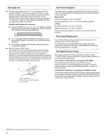
3. Use a combination wrench and channel lock pliers to attach the flexible connector to the adapters. Check that connector is not kinked. IMPORTANT: All connections must be wrench-tightened. Do not make connections to the gas regulator too tight. Making the connections too tight may crack the regulator and cause a gas leak. Do not allow the regulator to turn when tightening fittings. No appliance/obstructions below cooktop Suggested installation to avoid interference below cooktop 4. Install the pressure regulator with the arrow pointing in the direction toward the bottom of the cooktop base and in a position where you can reach the regulator access cap. B A C D A A B C B D C E D E F G H F G I H J I K A. Manifold entrance B. Gas pressure regulator C. Use pipe-joint compound. D. Adapter (must have ½" male pipe thread) E. Flexible connector F. Adapter G. Use pipe-joint compound. H. Manual gas shutoff valve I. ½" or ¾" gas pipe A. Manifold entrance B. ³⁄₈" elbow C. Use pipe-joint compound. D. Adapter (must have ³⁄₈" male pipe thread) E. Flexible connector (pass through wall between cabinets) F. Adapter (must have ³⁄₈" male pipe thread) G. Use pipe-joint compound. H. Appliance pressure regulator (supplied) I. ½" or ¾" gas pipe J. Manual gas shutoff valve K. ½" or ¾" gas pipe A. Access cap B. Rear of cooktop C. Gas pressure regulator D. Up arrow. The regulator must be installed with the arrow pointing toward the cooktop bottom. Use only pipe-joint compound made for use with Natural and LP gas. Do not use TEFLON® tape. You will need to determine the fittings required depending on your installation. Complete Connection 1. Open the manual shutoff valve in the gas supply line. The valve is open when the handle is parallel to the gas pipe. A B A. Closed valve B. Open valve 2. Test all connections by brushing on an approved noncorrosive leak-detection solution. Bubbles will show a leak. Correct any leak found. 3. Remove surface burner caps, burner base and grates from parts package. Align notches in burner caps with pins in burner base. Align orifice holder in burner base with igniter electrode. Burner caps should be level when properly positioned. If burner caps are not properly positioned, surface burners will not light. Place burner grates over burners and caps. B C D E A A. Orifice holder B. Burner cap C. Gas tube opening D. Burner base E. Igniter electrode 10
-
 1
1 -
2
-
3
-
4
-
 5
5 -
 6
6 -
 7
7 -
 8
8 -
 9
9 -
 10
10 -
 11
11 -
 12
12 -
 13
13 -
 14
14 -
 15
15 -
16
-
17
-
18
-
19
-
20
-
21
-
22
-
23
-
24
 |
 |
