Whirlpool WEC310SAGS Installation Instructions
Whirlpool WEC310SAGS Manual
 |
View all Whirlpool WEC310SAGS manuals
Add to My Manuals
Save this manual to your list of manuals |
Whirlpool WEC310SAGS manual content summary:
- Whirlpool WEC310SAGS | Installation Instructions - Page 1
INSTRUCTIONS FRONT CONTROL ELECTRIC RANGES Table of Contents RANGE SAFETY 2 INSTALLATION REQUIREMENTS 3 Tools and Parts 3 Location Requirements 3 Electrical Requirements - U.S.A. Only 5 INSTALLATION INSTRUCTIONS 6 Unpack Range 6 Install Anti-Tip Bracket 6 Adjust Leveling Legs 7 Level Range - Whirlpool WEC310SAGS | Installation Instructions - Page 2
foot is engaged in the slot of the anti-tip bracket. Re-engage anti-tip bracket if range is moved. Do not operate range without anti-tip bracket installed and engaged. Failure to follow these instructions can result in death or serious burns to children and adults. Anti-Tip Bracket To verify the - Whirlpool WEC310SAGS | Installation Instructions - Page 3
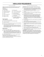
the instructions provided with model/serial/rating plate. The model/serial/rating plate is located behind the oven door on the top right-hand side of the oven frame. ■■ The range range, see "Install Anti-Tip Bracket" section. ■■ Grounded electrical supply is required. See the appropriate "Electrical - Whirlpool WEC310SAGS | Installation Instructions - Page 4
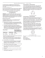
NFPA 501A or with local codes. In Canada, the installation of this range must conform with the current standards CAN/CSA-A240-latest edition, or "Electrical Connection - U.S.A. Only" section. Product Dimensions These instructions cover several models. Your model may appear different from the models - Whirlpool WEC310SAGS | Installation Instructions - Page 5
of electric shock. Check with a qualified electrician or service technician if electrical connection you will be using and follow the instructions provided for it here. ■■ Range must be connected to the proper electrical voltage and frequency as specified on the model/serial/rating plate. The model - Whirlpool WEC310SAGS | Installation Instructions - Page 6
the floor behind the range to support the range when it is laid on its back. 4. Using two or more people, firmly grasp the range and gently lay anti-tip bracket if range is moved. Do not operate range without anti-tip bracket installed and engaged. Failure to follow these instructions can result in - Whirlpool WEC310SAGS | Installation Instructions - Page 7
. Failure to follow these instructions can result in death or serious burns to children and adults. 1. If range height adjustment is necessary, use a wrench or pliers to loosen the four leveling legs. This may be done with the range on its back or with the range supported on two legs after the - Whirlpool WEC310SAGS | Installation Instructions - Page 8
model, remove plastic tag holding three 10-32 hex nuts from the middle post of the terminal block. 2. If range range. Pull the bottom of the cover toward you and out to remove cover from range. A. UL Listed strain relief 5. Complete installation following instructions for your type of electrical - Whirlpool WEC310SAGS | Installation Instructions - Page 9
post with one of the 10-32 hex nuts. A E 4-wire receptacle (NEMA type 14-50R) A UL Listed, 250-volt minimum, 40- or 50-amp, range power supply cord 4-Wire Connection: Power Supply Cord 3-Wire Connection: Power Supply Cord Use this method only if local codes permit connecting chassis ground - Whirlpool WEC310SAGS | Installation Instructions - Page 10
post with one of the 10-32 hex nuts. Electrical Shock Hazard Disconnect power before servicing. Use 8 gauge copper or 6 gauge aluminum wire. Electrically ground range. Failure to follow these instructions can result in death, fire, or electrical shock. Direct Wire Strain Relief 1. Disconnect power - Whirlpool WEC310SAGS | Installation Instructions - Page 11
your model, following instructions for your type of electrical connection: 4-wire (recommended) 3-wire (if 4-wire is not available) Electrical Connection Options wires through the conduit on cord/conduit plate on bottom of range. Allow enough slack to easily attach the wiring to the terminal - Whirlpool WEC310SAGS | Installation Instructions - Page 12
screwdriver to remove the ground-link screw from the back of the range. Save the ground-link screw and the end of the ground link under the screw. 3. Pull the wires through the strain relief on bottom of range. Allow enough slack to easily attach wiring to the terminal block. A B F - Whirlpool WEC310SAGS | Installation Instructions - Page 13
as shown in the following Bare Wire Torque Specifications chart. A 5. Use a hex or Phillips screwdriver to connect the bare (green) ground wire to the range with the ground-link screw and ground-link section. The ground wire must be attached over the ground-link section and must not contact any - Whirlpool WEC310SAGS | Installation Instructions - Page 14
is necessary, make sure the oven is off and cool. Then, follow these instructions. The oven door is heavy. To Remove: 1. Open oven door all the Reinstall the access panel by aligning the studs with the keyhole slots on the range. Press the toe panel forward into the slots and push downward to enage - Whirlpool WEC310SAGS | Installation Instructions - Page 15
to verify the electrical supply. 10. When the range has been on for 5 minutes, check for heat. If the range is cold, turn off the range and contact a qualified electrician. If You Need Assistance or Service: Please reference the "Warranty" section of the User Guide to contact service. 15 - Whirlpool WEC310SAGS | Installation Instructions - Page 16
W11097823B ©2017 All rights reserved. 04/17
-
 1
1 -
 2
2 -
 3
3 -
 4
4 -
 5
5 -
 6
6 -
 7
7 -
8
-
9
-
10
-
11
-
12
-
13
-
14
-
15
-
16
 |
 |

IMPORTANT:
Save for local electrical inspector's use.
W11097823B
INSTALLATION INSTRUCTIONS
FRONT CONTROL ELECTRIC RANGES
Table of Contents
RANGE SAFETY
.............................................................................
2
INSTALLATION REQUIREMENTS
.................................................
3
Tools and Parts
.............................................................................
3
Location Requirements
................................................................
3
Electrical Requirements - U.S.A. Only
.........................................
5
INSTALLATION INSTRUCTIONS
...................................................
6
Unpack Range
..............................................................................
6
Install Anti-Tip Bracket
.................................................................
6
Adjust Leveling Legs
....................................................................
7
Level Range
..................................................................................
8
Electrical Connection - U.S.A. Only
.............................................
8
Verify Anti-Tip Bracket Is Installed and Engaged
......................
14
Remove/Reinstall Toe Panel
......................................................
14
Oven Door
..................................................................................
14
Complete Installation
.................................................................
15