Whirlpool WED6400SB Installation Instructions
Whirlpool WED6400SB - Cabrio 7.0 Cu Ft Capacity Electric Dryer Manual
 |
UPC - 883049025094
View all Whirlpool WED6400SB manuals
Add to My Manuals
Save this manual to your list of manuals |
Whirlpool WED6400SB manual content summary:
- Whirlpool WED6400SB | Installation Instructions - Page 1
ELECTRIC DRYER INSTALLATION INSTRUCTIONS U.S.A. ONLY Para una version de estas instrucciones en español, visite www.Whirlpool.com TABLE OF CONTENTS TABLE OF CONTENTS 1 DRYER SAFETY 1 INSTALLATION REQUIREMENTS 2 Tools and Parts 2 Optional Equipment 2 Location Requirements 3 ELECTRIC DRYER - Whirlpool WED6400SB | Installation Instructions - Page 2
Parts Gather the required tools and parts before starting installation. Read and follow the instructions provided with any tools listed here. Steam Models ■ Flat-blade screwdriver ■ #2 Phillips screwdriver ■ Adjustable wrench that opens to 1" (25 mm) or hex-head socket wrench (for adjusting dryer - Whirlpool WED6400SB | Installation Instructions - Page 3
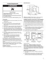
See "Electrical Requirements." ■ A sturdy floor to support total dryer weight of 200 lbs. (90.7 kg). Also consider combined weight of a companion appliance. ■ A level floor with maximum slope of 1" (25 mm) under entire dryer. If slope is greater than 1" (25 mm), install Extended Dryer Feet Kit, Part - Whirlpool WED6400SB | Installation Instructions - Page 4
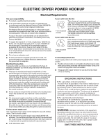
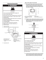
Electrical Connection To properly install your dryer, you must determine the type of electrical connection you will be using and follow the instructions provided for it here. ■ This dryer power supply cord with ring or spade terminals and UL listed strain relief. The 4-wire power supply cord, at - Whirlpool WED6400SB | Installation Instructions - Page 5
is inside strain relief. Strain relief should have a tight fit with the dryer cabinet and be in a horizontal position. Do not further tighten strain relief gauge solid copper wire. Use a UL listed strain relief. Disconnect power before making electrical connections. Connect neutral wire (white or - Whirlpool WED6400SB | Installation Instructions - Page 6
instructions for your type of electrical connection: 4-wire (recommended) 3-wire (if 4-wire is not available) Electrical Connection Options If your home has: And you will be Go to Section connecting to: 4-wire receptacle (NEMA Type 14-30R) A UL listed, 120/240-volt minimum, 30-amp, dryer - Whirlpool WED6400SB | Installation Instructions - Page 7
wire (green or bare) of power supply cord D. 3/4" (19 mm) UL listed strain relief E. Center, silver-colored terminal block screw F. Neutral wire (white into slot of dryer rear panel. Secure cover with hold-down screw. 7. You have completed your electrical connection. Now go to "Venting Requirements - Whirlpool WED6400SB | Installation Instructions - Page 8
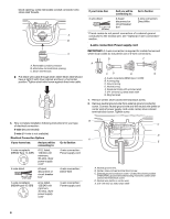
into slot of dryer rear panel. Secure cover with hold-down screw. 7. You have completed your electrical connection. Now go to "Venting ) B. 3-wire plug C. Neutral prong D. Spade terminals with up turned ends E.3/4" (19 mm) UL listed strain relief F. Ring terminals G. Neutral (white or center wire) - Whirlpool WED6400SB | Installation Instructions - Page 9
Neutral wire (white or center wire) E. 3/4" (19 mm) UL listed strain relief F. Grounding path determined by a qualified electrician 3. Connect the cover into slot of dryer rear panel. Secure cover with hold-down screw. 6. You have completed your electrical connection. Now go to "Venting Requirements - Whirlpool WED6400SB | Installation Instructions - Page 10
vent. Failure to follow these instructions can result in death or fire extended and supported when the dryer is in its or flexible heavy metal vent. ■ Review vent system chart. Modify existing Whirlpool Service. For more information, see the "Assistance or Service" section in your Use and Care Guide - Whirlpool WED6400SB | Installation Instructions - Page 11
installations are shown. Refer to the manufacturer's instructions. A. Over-the-top installation (also available Service" section in your Use and Care Guide to order. ■ Over-the-Top Installation: Part Number 4396028 ■ Periscope Installation (For use with dryer vent to wall vent mismatch): Part - Whirlpool WED6400SB | Installation Instructions - Page 12
will help to achieve the best drying performance. Vent system chart NOTE: Side and bottom exhaust installations have a 90º turn inside the dryer. To determine maximum exhaust length, add one 90º turn can be attached directly to cold water faucet, go to Step 6. If "Y" connector cannot be attached - Whirlpool WED6400SB | Installation Instructions - Page 13
parts are now installed. If there is an extra part, go Dryer Use" in your Use and Care Guide. 9. For power supply cord installation, plug into a grounded outlet. For direct wire installation, turn dryer. Over time, the buildup of lime scale may clog different parts of the water system, which will - Whirlpool WED6400SB | Installation Instructions - Page 14
the dryer's heater from turning on. See "Troubleshooting." If you receive an AF code, your dryer vent may be crushed or blocked. See "Troubleshooting." NOTE: You may notice an odor when the dryer is first heated. This odor is common when the heating element is first used. The odor will go away - Whirlpool WED6400SB | Installation Instructions - Page 15
by a power failure? Press and hold START to restart the dryer. ■ "L2" Diagnostic Code (low or no line voltage condition): The drum will turn, but there may be a problem with your home power supply keeping the dryer's heater from turning on. The dryer will continue to run when this diagnostic code - Whirlpool WED6400SB | Installation Instructions - Page 16
Electrical Connection" for details. Select a Timed Dry heated cycle, and restart the dryer. If the message persists, consult a qualified electrician. ■ "AF" (low airflow condition): The dryer will has too many turns. Long venting will increase drying times. See the Installation Instructions. ■ Is the
-
 1
1 -
 2
2 -
 3
3 -
 4
4 -
 5
5 -
 6
6 -
 7
7 -
8
-
9
-
10
-
11
-
12
-
13
-
14
-
15
-
16
 |
 |
ELECTRIC DRYER INSTALLATION INSTRUCTIONS
U.S.A. ONLY
Para una version de estas instrucciones en español, visite www.Whirlpool.com
TABLE OF CONTENTS
TABLE OF CONTENTS
..................................................................
1
DRYER SAFETY
..............................................................................
1
INSTALLATION REQUIREMENTS
................................................
2
Tools and Parts
............................................................................
2
Optional Equipment
.....................................................................
2
Location Requirements
................................................................
3
ELECTRIC DRYER POWER HOOKUP
.........................................
4
Electrical Requirements
...............................................................
4
Electrical Connection
...................................................................
5
VENTING
........................................................................................
10
Venting Requirements
................................................................
10
Plan Vent System
.......................................................................
11
Install Vent System
.....................................................................
12
INSTALL LEVELING LEGS
...........................................................
12
CONNECT VENT
...........................................................................
12
CONNECT INLET HOSE (STEAM MODELS)
..............................
13
LEVEL DRYER
..............................................................................
13
COMPLETE INSTALLATION
.......................................................
13
Reverse Door Swing
...................................................................
14
TROUBLESHOOTING
.................................................................
15
Dryer Operation
..........................................................................
15
Dryer Results
..............................................................................
16
W10267633A
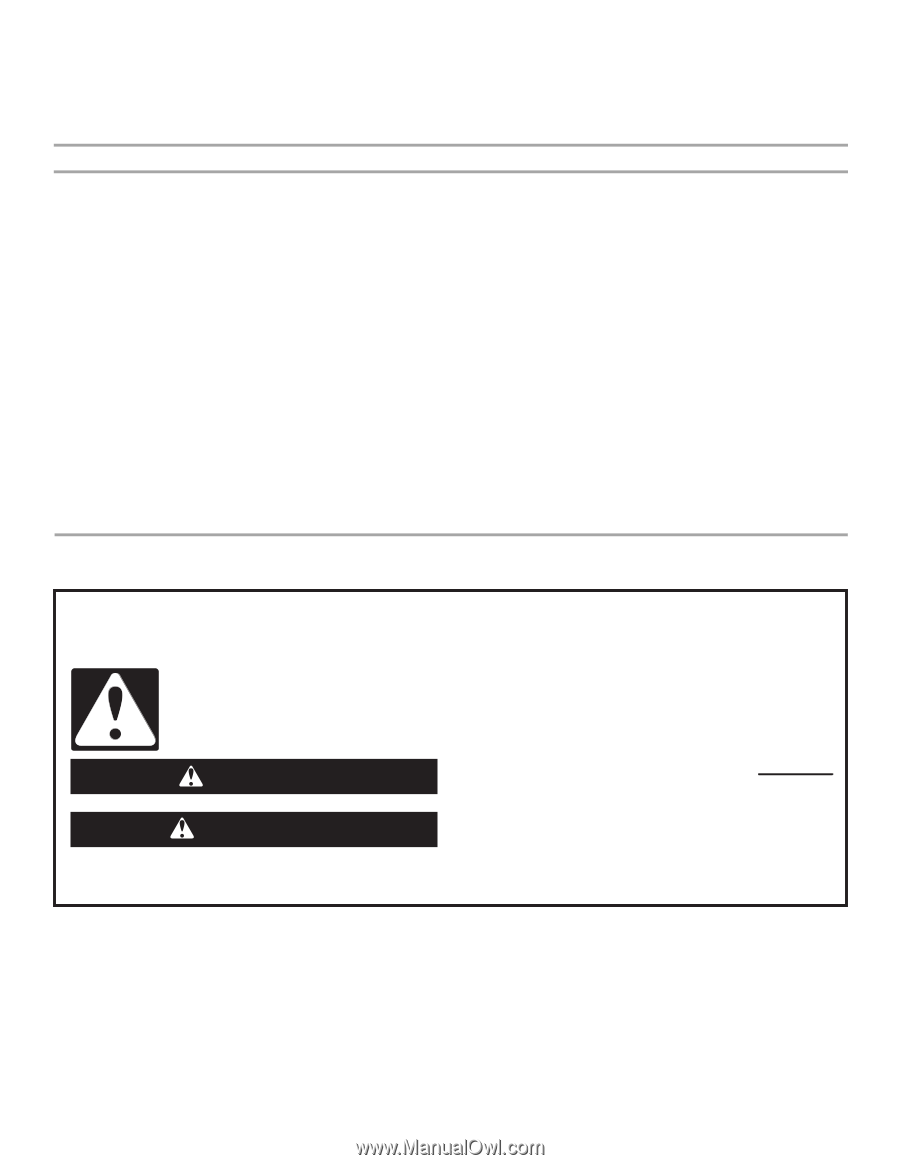
DRYER SAFETY
You
You can be kille
d
or seriously injure
d
if you
d
on't imme
d
iately
can be kille
d
or seriously injure
d
if you
d
on't follow
All
s
afety me
ss
age
s
will tell you what the potential hazard i
s
, tell you how to reduce the chance of injury, and tell you what can
happen if the in
s
truction
s
are not followed.
Your safety an
d
the safety of others are very important.
We have provided many important
s
afety me
ss
age
s
in thi
s
manual and on your appliance. Alway
s
read and obey all
s
afety
me
ss
age
s
.
Thi
s
i
s
the
s
afety alert
s
ymbol.
Thi
s
s
ymbol alert
s
you to potential hazard
s
that can kill or hurt you and other
s
.
All
s
afety me
ss
age
s
will follow the
s
afety alert
s
ymbol and either the word “DANGER” or “WARNING.”
The
s
e word
s
mean:
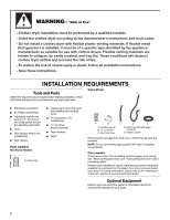
follow instructions.
instructions.
DANGER
WARNING