Whirlpool WED70HEBW Ventilation Specification - Page 5
Maximum Allowable Back Pressure for Dryer
 |
View all Whirlpool WED70HEBW manuals
Add to My Manuals
Save this manual to your list of manuals |
Page 5 highlights
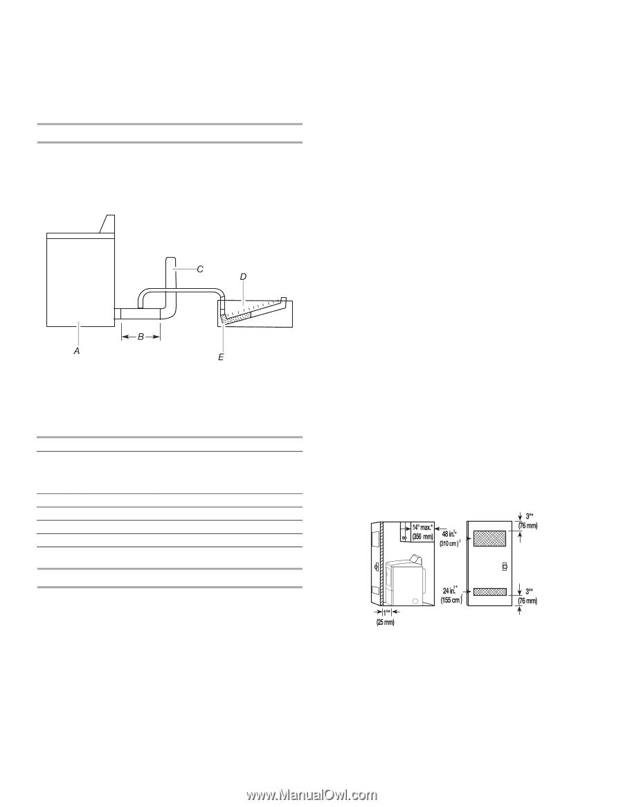
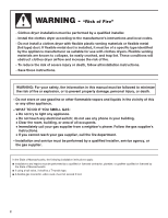
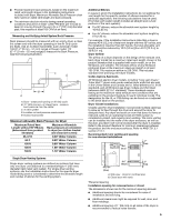
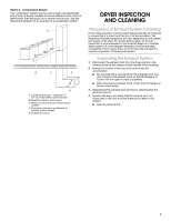
■ Provide maximum back pressure, based on the maximum rated vent length shown in the Installation Instructions included with dryer. Maximum Allowable Back Pressure chart lists maximum rated vent length and back pressure. ■ The minimum duct air velocity during normal operating conditions should be at least 1,200 FPM (feet per minute) to keep lint moving through the vent. (In a 4" (102 mm) diameter pipe, this requires at least 105 CFM of air flow.) Measuring and Verifying Actual System Back Pressure Back pressure should be measured with an empty dryer, a clean lint screen and with the dryer operating in the Air Only cycle (no heat). Use an inclined manometer, such as Dwyer model 102 (0"-2" [0 mm - 51 mm] range) or Dwyer model 172 (0"-1" [0 mm - 25 mm] range) to measure the Back Pressure. See the following illustration. A. Dryer - empty and running on Air Only cycle B. 12" (305 mm) min. of straight pipe - measure back pressure from the center C. To vent system D. Location on back pressure measurement E. Inclined manometer Maximum Allowable Back Pressure for Dryer Maximum Rated Vent Length without 90° Elbows (determined from product literature) Maximum Allowable Back pressure at connection to dryer (no clothes loaded and clean lint screen) 36-37 ft 0.40" Water Column 64 ft 0.60" Water Column 100 ft 0.80" Water Column 120 ft 1.00" Water Column 130 ft 1.10" Water Column Additional Elbows In cases in which the Installation Instructions do not address the vent length for the specific number of elbows required for a particular application, the following calculations may be used. (The total vent system length includes all straight and curved portions of the vent system.): ■ For 90° elbows, reduce the allowable vent system length by 10 ft (3.05 m). ■ For 45° elbows, reduce the allowable vent system length by 6 ft (1.83 m). For example, if the Installation Instructions state that a dryer is allowed 40 ft (12.2 m) of total vent length with two 90° bends, and the installation requires three 90° bends, the total allowable vent length would be reduced by 10 ft (3.0 m) (from 40 ft [12.2 m] to 30 ft [9.1 m]). Dryer Airflow The airflow of a dryer depends on the design of the exhaust vent. Each dryer model has a maximum rated vent length, shown in the product literature that is supplied with each model, or on the Whirlpool.com website. The exhaust airflow of any Whirlpool produced dryer at the maximum rated vent length is at least 105 CFM. The maximum airflow is 230 CFM. This includes standard vent and long vent dryer models. Codes Agency Approvals All Whirlpool electric dryer models, including "long vent dryers," Turbo Vent™ dryers and combo washer/dryer units that are sold in the United States and Canada are UL listed (reference UL 2158 standard), and all Whirlpool gas dryer models are CSA listed (reference ANSI Z21.5.1 standard). These standards require testing at the maximum-rated exhaust vent conditions that are published in the product literature for each individual model. The designation for the UL or CSA listing can be found on or adjacent to the serial label on the product. Dryer Closet Installations Closets used for dryer installation must provide multiple openings to allow air to flow through the dryer and around the dryer to dissipate heat. Any dryer enclosure or room that does not have an inlet and outlet for an operating forced air HVAC system is considered a closet, and requires room venting. The room venting can be installed into the walls of the dryer enclosure, as well as the door, provided it will not be blocked after the dryer is installed. Refer to the product literature for minimum clearances between the product and the enclosure surfaces. Refer to ANSI Z21.5.1 section 2.14.1. Recommended room venting and spacing for non-stacked installations Single Dryer Venting Systems Single dryer venting systems are defined as systems that have only one dryer unit attached to a residential-type 4" (102 mm) diameter rigid metal vent system. For single dryer venting systems, see the Installation Instructions for the specific dryer model being used or considered to determine the allowable length and number of elbows for the venting system. A. Side view - closet or confined area B. Closet door with vents *Required spacing Installation spacing for recessed area or closet The dimensions shown are for the minimum spacing allowed. ■ Additional spacing should be considered for ease of installation and servicing. ■ Additional clearances might be required for wall, door, and floor moldings. ■ Additional spacing of 1" (25 mm) on all sides of the dryer is recommended to reduce noise transfer. 5
-
 1
1 -
 2
2 -
 3
3 -
 4
4 -
 5
5 -
 6
6 -
 7
7 -
 8
8
 |
 |