Whirlpool WED7505FW Installation Guide - Page 5
Location Requirements
 |
View all Whirlpool WED7505FW manuals
Add to My Manuals
Save this manual to your list of manuals |
Page 5 highlights
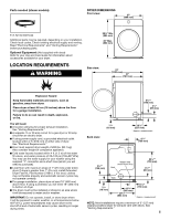
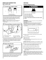
Parts needed (steam models): DRYER DIMENSIONS Front view: 27" (686 mm) 5' (1.52 m) inlet hose Additional parts may be required, depending on your installation. Check local codes. Check existing electrical supply and venting. Read "Electrical Requirements" and "Venting Requirements" before purchasing parts. Optional Equipment: (Not supplied with dryer) Refer to your Use and Care Guide for information about accessories available for your dryer. 383/4" Min. (984 mm) 39" Max. (990 mm) LOCATION REQUIREMENTS Side view: You will need: ■■A location allowing for proper exhaust installation. See "Venting Requirements." ■■A separate 15 or 20 amp circuit for a gas dryer or 30 amp circuit for an electric dryer. ■■If using power supply cord, a grounded electrical outlet located within 2 ft. (610 mm) of either side of dryer. See "Electrical Requirements." ■■Floor must support dryer weight of 200 lbs. (90.7 kg). Also consider weight of companion appliance. ■■Cold water faucets located within 4 ft. (1.2 m) of the water fill valves, and water pressure of 20-120 psi (138-827 kPa). You may use the water supply for your washer using the supplied "Y" connector and a short hose (which you will need to purchase). ■■Level floor with maximum slope of 1" (25 mm) under entire dryer. If slope is greater than 1" (25 mm), install Extended Dryer Feet Kit, Part Number 279810. If not level, clothes may not tumble properly and automatic sensor cycles may not operate correctly. ■■For garage installation, place dryer at least 18" (460 mm) above floor. If using a pedestal, you will need 18" (460 mm) to bottom of dryer. ■■The dryer must not be installed or stored in an area where it will be exposed to water and/or weather. IMPORTANT: Do not operate, install, or store dryer where it will be exposed to water, weather, or at temperatures below 40°F (4°C). Lower temperatures may cause dryer not to shut off at end of automatic sensor cycles, resulting in longer drying times. Back view: * Approx. measurement 61/4" (159 mm) 53/4"* (146 mm) Vent Water inlet (Steam Models Only) 297/8"* (759 mm) 31/2"* (89 mm) Gas 3/4"* (18 mm) 143/8" (365 mm) 253/4" (654 mm) 61/8"* (156 mm) * Approx. measurement NOTE: Most installations require a minimum of 5" (127 mm) clearance behind dryer for exhaust vent with elbow. See "Venting Requirements." 5
-
 1
1 -
 2
2 -
 3
3 -
 4
4 -
 5
5 -
 6
6 -
 7
7 -
 8
8 -
 9
9 -
 10
10 -
 11
11 -
12
-
13
-
14
-
15
-
16
-
17
-
18
-
19
-
20
-
21
-
22
-
23
-
24
-
25
-
26
-
27
-
28
-
29
-
30
-
31
-
32
-
33
-
34
-
35
-
36
-
37
-
38
-
39
-
40
-
41
-
42
-
43
-
44
-
45
-
46
-
47
-
48
 |
 |
