Whirlpool WED9500T Dimension Guide - Page 3
Exhaust Venting, Undercounter Installation, Product Model Numbers - dryer
 |
View all Whirlpool WED9500T manuals
Add to My Manuals
Save this manual to your list of manuals |
Page 3 highlights
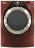
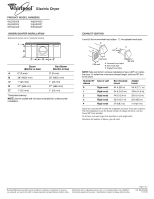
® Electric Dryer PRODUCT MODEL NUMBERS WED9200S WED9300V WED9400S WED9400V WED9500T WED9600T UNDERCOUNTER INSTALLATION Dimensions shown are for minimum spacing. A B C* D E* Steam (Electric or Gas) Non-Steam (Electric or Gas) A 0" (0 mm) 0" (0 mm) B 38" (9652 mm) 38" (9652 mm) C* 1" (25 mm) 1" (25 mm) D 27" (686 mm) E* 1" (25 mm) 27" (686 mm) 1" (25 mm) *Required spacing NOTE: Some models are not recommended for undercounter installation. EXHAUST VENTING A and B: Recommended hood styles. C: Acceptable hood style. B 4" C A (102 mm) 4" (102 mm) 4" (102 mm) A. Louvered hood style B. Box hood style C. Angled hood style 2½" (64 mm) NOTE: Side and bottom exhaust installations have a 90º turn inside the dryer. To determine maximum exhaust length, add one 90º turn to the chart. Number 90º Type of vent elbows Box /louvered Angled hoods hoods 0 Rigid metal 64 ft (20 m) 58 ft (17.7 m) 1 Rigid metal 54 ft (16.5 m) 48 ft (14.6 m) 2 Rigid metal 44 ft (13.4 m) 38 ft (11.6 m) 3 Rigid metal 35 ft (10.7 m) 29 ft (8.8 m) 4 Rigid metal 27 ft (8.2 m) 21 ft (6.4 m) Select the route that will provide the straightest and most direct path outdoors. Plan the installation to use the fewest number of elbows and turns. Use the fewest 90° turns possible. Do not use vent runs longer than specified in vent length chart. Determine the number of elbows you will need. Because Whirlpool Corporation policy includes a continuous commitment to improve Dimensions are for planning purposes only. For complete details, see Installation our products, we reserve the right to change materials and specifications without notice. Instructions packed with product. Specifications subject to change without notice. Page 3 of 3 Ref. W10224585 11-07-08
-
 1
1 -
 2
2 -
 3
3
 |
 |
