Whirlpool WGE555S0BB Dimension Guide - Page 1
Whirlpool WGE555S0BB Manual
 |
View all Whirlpool WGE555S0BB manuals
Add to My Manuals
Save this manual to your list of manuals |
Page 1 highlights
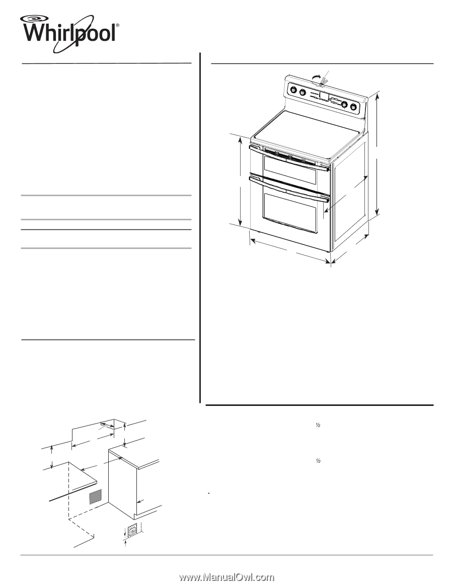
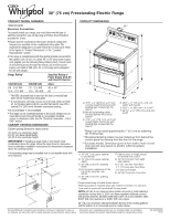
30" (76 cm) Freestanding Electric Range PRODUCT MODEL NUMBERS PRODUCT DIMENSIONS WGE555S0B Electrical Connection: To properly install your range, you must determine the type of electrical connection you will be using and follow the instructions provided for it here. q Range must be connected to the proper electrical voltage and frequency as specified on the model/serial rating plate. The model/serial rating plate is located behind the control panel. Refer to the figures in "Product Dimensions" in the "Location Requirements" section. q This range is manufactured with the neutral terminal connected to the cabinet. Use a 3-wire, UL listed, 40- or 50- amp power supply cord (pigtail) (see the following Range Rating chart). If local codes do not permit ground through the neutral, use a 4-wire power supply cord rated at 250 volts, 40- or 50-amps and investigated A* for use with ranges. Range Rating* Specified Rating of Power Supply Cord Kit and Circuit Protection B** C* D 120/240 Volts 8.8 - 16.5 KW 16.6 - 22.5 KW 120/208 Volts 7.8 - 12.5 KW 12.6 - 18.5 KW Amps 40 or 50** 50 ** The NEC calculated load is less than the total connected load listed on the model/serial rating plate. ** If connecting to a 50-amp circuit, use a 50-amp rated cord with kit. For 50-amp rated cord kits, use kits that specify use with a nominal 1³⁄₈" (34.9 mm) diameter connection opening. q A circuit breaker is recommended. q The range can be connected directly to the circuit breaker box (or fused disconnect) through flexible or nonmetallic sheathed, copper or aluminum cable. See the "Electrical Connection - U.S.A. Only" section. CABINET OPENING DIMENSIONS Cabinet opening dimensions shown are for: 25" (63.5 cm) countertop depth, 24" (61 cm) base cabinet depth, 36" (91.4 cm) countertop height IMPORTANT: If installing a range hood or microwave hood combination above the range, follow the range hood or microwave hood combination installation instructions for dimensional clearances above the cooktop surface. F E*** A. 35¾" ± ½8" (90.8 cm ± 0.3 cm) cooktop height (minimum) with leveling legs screwed all the way in* B. Model/serial/rating plates (located behind the control panel)** C. 47½8" ± ½8" (119.7 cm ± 0.3 cm) overall height (minimum) with leveling legs screwed all the way in* D. 28½" ± ¼" (72.4 cm ± 0.6 cm) depth with handle E. 26½8" ± ½8" (66.4 cm ± 0.3 cm)*** F. 2915¼16" ± ¼16" (76.0 cm ± 0.2 cm) width *Range can be raised approximately 1" (2.5 cm) by adjusting the leveling legs. **Model/serial/rating plates may be rotated up from behind the control panel for viewing from the front of the range. ***Excludes handle. Dimension given is from wall to front of oven door and will vary based on electric outlet receptacle installation. A freestanding range may be installed next to combustible walls with zero clearance. B D C A E A. 18" (45.7 cm) upper cabinet to countertop B. 13" (33.0 cm) upper cabinet depth C. 30" (76.2 cm) min. opening width D. For minimum clearance to the top of the cooktop, see NOTE. E. 30" (76.2 cm) min. opening width F. Cabinet door or hinge should not extend into cutout* G. 1 " (3.8 cm) min. from right side cabinet H. 2" (5.1 cm) min. from floor I. 7" (17.8 cm) min. from floor J. 8" (20.3 cm) width K. 3 " (8.91 cm) min. from floor J G I F H Proper positioning of outlet shown above. Nothing located in shaded areas can extend more than 1½" (3.8 cm) from wall or range will not slide all the way back. NOTE: 24" (61.0 cm) minimum when bottom of wood or metal cabinet is covered by not less than ¹⁄₄" (0.64 cm) flame retardant millboard covered with not less than No. 28 MSG sheet steel, 0.015" (0.4 mm) stainless steel, 0.024" (0.6 mm) aluminum or 0.020" (0.5 mm) copper. 30" (76.2 cm) minimum clearance between the top of the cooking platform K and the bottom of an uncovered wood or metal cabinet. Because Whirlpool Corporation policy includes a continuous commitment to improve Dimensions are for planning purposes only. For complete details, see Installation our products, we reserve the right to change materials and specifications without notice. Instructions packed with product. Specifications subject to change without notice. Ref. W10575959A 7/9/13
-
 1
1
 |
 |