Whirlpool WMH1162XVD Installation Instructions - Page 6
inPossible
 |
UPC - 883049147901
View all Whirlpool WMH1162XVD manuals
Add to My Manuals
Save this manual to your list of manuals |
Page 6 highlights
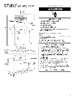
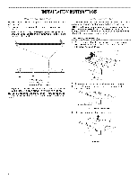
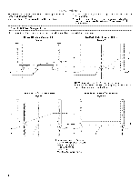
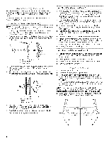
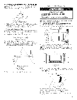
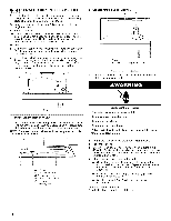
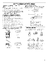
NinOstTatEllhI:fenmowicarollswtuadvoseevxeins.wt ithinthecabineotpeningd,onot Seeillustrationins"PossibWlealSl tudConfigurations." 1. Usingastudfindelro, catetheedgesofthewallstud(sw)ithin theopening. 2. MeaacrhktshtuecdceennteteorSrfe.eaecillhustsutrda,atniodindnsr"aPwoaspsluibmWleblainlSledtuodwn Configurations." Possible Wall Stud Configurations These depictions show examples of preferred installation configurations with the mounting plate. No Wall Studs at Corner Holes Figure 1 No Wall Studs at Corner Holes Figure 2 i i i S_ i i i i i I:. ..... c I i F1 i _ _ tJ I A ! _, ,f i i i i i i C I ,D i E --'Jf"f'f'_ i [_/ i i F = Yi m i " 1 ii ii i Wall Stud at One Corner Hole Figure 3 E F i i i NOTE: If wall stud is within 6" (15.2 cm) of the vertical centerline (see "Mark Rear Wall" section), only recirculation or roof venting installation can be done. Wall Studs at Both Corner Holes Figure 4 i i i i i i i i i ii 1i _D i i i A. Corner holes (on mounting plate) B. Cabinet opening vertical centerline C. Wall stud centerlines D. Holes for lag screws E. Support tabs F. Mounting plate center markers 6
-
 1
1 -
 2
2 -
 3
3 -
 4
4 -
 5
5 -
 6
6 -
 7
7 -
 8
8 -
 9
9 -
 10
10 -
 11
11 -
 12
12
 |
 |
