Whirlpool WOC95EC0A Instruction Sheet
Whirlpool WOC95EC0A Manual
 |
View all Whirlpool WOC95EC0A manuals
Add to My Manuals
Save this manual to your list of manuals |
Whirlpool WOC95EC0A manual content summary:
- Whirlpool WOC95EC0A | Instruction Sheet - Page 1
for Blower Noise Reduction Kit WARNING electrical Shock hazard Kit Contains: 2 Blower Brackets (1 left and 1 right) 1 Instruction Sheet disconnect power before servicing. INSTALLATION INSTRUCTIONS Replace all parts and panels before operating. Failure to do so can result in death 5. Remove - Whirlpool WOC95EC0A | Instruction Sheet - Page 2
et panneaux avant de faire la remise en marche. 5. Retirer les 4 vis (2 de chaque côté) fixant le ventilateur aux INSTRUCTIONS D'INSTALLATION Le non-respect de ces instructions peut brides de fixation du ventilateur. Voir la Figure 3. causer un décès ou un choc électrique. Préparation du four
-
 1
1 -
 2
2
 |
 |
Instruction Sheet W10883107
Rev A
4/16
Instruction Sheet
for Blower Noise Reduction Kit
Kit Contains:
1.
Disconnect power before servicing.
2
Blower Brackets (1 left and 1 right)
1
Instruction Sheet
© Whirlpool Corporation 2016
(All Rights Reserved)
WARNING
Electrical Shock Hazard
Disconnect power before servicing.
Failure to do so can result in death
or electrical shock.
Replace all parts and panels before
operating.
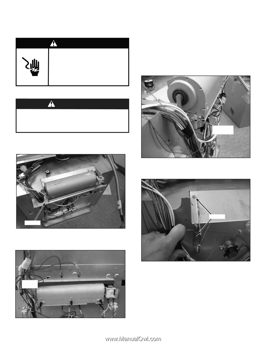
6.
Remove blower brackets from unit. This will require a wrench
to reach screws between cavities on double wall ovens.
See
Figure 4
.
7.
Install blower brackets from kit.
8.
Reattach 4 screws connecting blower to blower brackets.
9.
Reconnect all blower wiring.
10. Reattach air divider, panels, and top cover (and U-shaped
cover, if applicable) and reinstall unit in cabinet.
11. Replace all parts and panels.
12. Reconnect power.
4.
Disconnect blower from wire harness. On double ovens, also
remove the U- shaped cover located near the lower blower.
See
Figure 2
.
— 1 —
FIGURE 4
WARNING
Excessive Weight Hazard
Use two or more people to move and install oven.
Failure to do so can result in back or other injury.
2.
Remove unit from cabinet.
3.
Remove rear panels, top cover, and air divider from unit.
See
Figure 1
.
FIGURE 1
AIR DIVIDER
5.
Remove 4 screws (2 on each side) connecting blower to
blower brackets. See
Figure 3
.
FIGURE 3
(2) SCREWS ON
EACH SIDE
(3) SCREWS
FIGURE 2
U-SHAPED
COVER