Whirlpool WRS571CIDM Use & Care Guide - Page 4
Warning - parts
 |
View all Whirlpool WRS571CIDM manuals
Add to My Manuals
Save this manual to your list of manuals |
Page 4 highlights
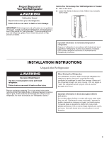
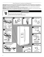
Door Removal, Leveling and Alignment Gather the required tools and parts and read all instructions before starting installation. Save these instructions for future reference. IMPORTANT: The graphics on this page are for models with the ice storage bin on the door. On models with the ice storage bin inside the freezer, the wiring and water dispenser tubing configurations are simpler than what is shown in these graphics. Please read all instructions on the next few pages for more information. NOTE: Before moving your product into your home, measure the doorway of your home to see whether you need to remove the refrigerator and freezer doors. If door removal is necessary, see the instructions below. IMPORTANT: Before you begin, turn the refrigerator control OFF or turn cooling off. Unplug refrigerator or disconnect power. Remove food, the ice storage bin (on some models), and any adjustable door or utility bins from doors. WARNING Electrical Shock Hazard Disconnect power before removing doors. Failure to do so can result in death or electrical shock. 3 Wiring Connection 4 Top Left Hinge AB CD EF A. P-clamp B. Routing Plate C. Electrical Housing D. Wiring Clip E. Grommets F. Wiring Plugs 2A Water Dispenser Tubing Connection (Style 1) A A A. Do Not Remove Screws. 5 Door Removal 6 Top Right Hinge A A A. Do Not Remove Screws. 7 Bottom Hinges (Left and Right) A A A. Face of Fitting 2B Water Dispenser Tubing Connection (Style 2) 8 Leveling A B Raise Lower C A. Bottom Hinge B. Leveler Bracket C. Leveling Foot 1 Base Grille 9 Door Alignment (Bottom Right Hinge) Doors must be open to 90˚ A Raise Lower A. Alignment Screw 4
-
 1
1 -
 2
2 -
 3
3 -
 4
4 -
 5
5 -
 6
6 -
 7
7 -
 8
8 -
 9
9 -
 10
10 -
11
-
12
-
13
-
14
-
15
-
16
-
17
-
18
-
19
-
20
-
21
-
22
-
23
-
24
-
25
-
26
-
27
-
28
-
29
-
30
-
31
-
32
-
33
-
34
-
35
-
36
-
37
-
38
-
39
-
40
-
41
-
42
-
43
-
44
-
45
-
46
-
47
-
48
-
49
-
50
-
51
-
52
-
53
-
54
-
55
-
56
-
57
-
58
-
59
-
60
-
61
-
62
-
63
-
64
-
65
-
66
-
67
-
68
-
69
-
70
-
71
-
72
-
73
-
74
-
75
-
76
-
77
-
78
-
79
-
80
-
81
-
82
-
83
-
84
 |
 |
