Yamaha 01V96i Owner's Manual
Yamaha 01V96i Manual
 |
View all Yamaha 01V96i manuals
Add to My Manuals
Save this manual to your list of manuals |
Yamaha 01V96i manual content summary:
- Yamaha 01V96i | Owner's Manual - Page 1
Owner's Manual Keep This Manual For Future Reference. EN - Yamaha 01V96i | Owner's Manual - Page 2
Analog Input Spec 61 Analog Output Specs 61 Digital Input Spec 62 Digital Output Spec 62 I/O SLOT Spec 63 MIDI/USB/WORD CLOCK I/O Spec .... 64 Dimensions 64 Options 65 Rack Mounting the 01V96i Using RK1 Rack Mount Kit 65 Index 66 01V96i Block Diagram.......End of Manual 01V96i Level Diagram - Yamaha 01V96i | Owner's Manual - Page 3
alert the user to the presence of important operating and maintenance (servicing) instructions in the literature accompanying the product. IMPORTANT SAFETY INSTRUCTIONS 1 Read these instructions. 2 Keep these instructions. 3 Heed all warnings. 4 Follow all instructions. 5 Do not use this apparatus - Yamaha 01V96i | Owner's Manual - Page 4
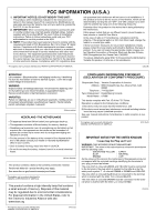
as indicated in the instructions contained in this manual, meets FCC requirements. Modifications not expressly approved by Yamaha may void your authority, granted by the FCC, to use the product. 2. IMPORTANT: When connecting this product to accessories and/ or another product use only high quality - Yamaha 01V96i | Owner's Manual - Page 5
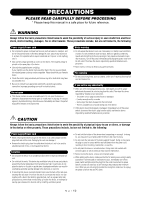
this manual in a safe place for future reference. WARNING user-serviceable parts. Do not open the device or attempt to disassemble the internal parts or modify them in any way. If it should appear to be malfunctioning, discontinue use immediately and have it inspected by qualified Yamaha service - Yamaha 01V96i | Owner's Manual - Page 6
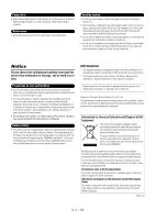
Low Battery!." In this case, immediately save the data to an external media using MIDI Bulk Dump, then have qualified Yamaha service personnel replace the backup battery. Information * The illustrations and screen displays as shown in this Owner's Manual are for instructional purposes only, and may - Yamaha 01V96i | Owner's Manual - Page 7
the Yamaha 01V96i Digital Mixing Console. The compact 01V96i Digital Console features 24-bit/96 kHz digital audio processing without compromise, as well as 40-channel simultaneous mixing. The 01V96i covers a broad range of needs and applications including multi-track recording, 2-channel mixdown - Yamaha 01V96i | Owner's Manual - Page 8
functionality, or fix problems. Firmware updates are performed with the product connected to a computer, so you must first install the "Yamaha Steinberg USB Driver" in your computer. Firmware updating is performed using update software. You can download the update software from the following website - Yamaha 01V96i | Owner's Manual - Page 9
SCENE DIO/SETUP MIDI UTILITY / INSERT/ PAN/ PAIR/ DELAY ROUTING GROUP PATCH DYNAMICS EQ EFFECT FADER MODE VIEW AUX 1 AUX 2 AUX 3 AUX 4 AUX 5 AUX 6 AUX 7 AUX 8 HOME (METER) LAYER 1-16 17-32 MASTER REMOTE Display Section (p. 13) OVER 0 -3 -6 -9 -12 -15 -18 -24 -30 -36 -48 STEREO STORE - Yamaha 01V96i | Owner's Manual - Page 10
16 button is turned off. 3 INSERT I/O connectors These unbalanced TRS phone-type connectors are used for channel insert ins and outs. Use a split cable to insert an external effects processor to AD input channels Input sensitivity is -16 dB to -60 dB when the Pad is off, and +4 dB to -40 dB when the - Yamaha 01V96i | Owner's Manual - Page 11
output line-level signals, and are typically used to connect an external recorder. When the AD15/16 selector in the AD Input sec- tion 3 [STEREO] fader This 100mm motorized fader adjusts the final output level of the Stereo Out. 1 SEL 2 ON 0 5 10 15 20 30 40 50 60 70 3 STEREO 01V96i-Owner's Manual - Yamaha 01V96i | Owner's Manual - Page 12
up.) You can now adjust the send level of signals routed from Input Channels to the corresponding Aux buses by using the faders. 2 [HOME] button This button recalls Meter pages that display Input Channel levels or Output Channel (Bus Out, Aux Out, Stereo Out) levels (see page 23). DISPLAY ACCESS - Yamaha 01V96i | Owner's Manual - Page 13
effects processors and use optional plug-in cards. B [VIEW] button This button displays a View page, enabling you to view and set mix parameters for a specific channel. Display Section 1 OVER 0 -3 -6 -9 -12 -15 -18 -24 -30 -36 -48 STEREO 2 3 LAYER Section LAYER 1-16 17-32 MASTER REMOTE - Yamaha 01V96i | Owner's Manual - Page 14
LOW-MID, LOW) of the channel selected by the [SEL] enables you to store the current mix settings. (See page 42 USER DEFINED KEYS Section 1 USER DEFINED KEYS 1 2 3 4 5 6 7 8 1 [1]-[8] buttons You can assign any of the 167 functions to these User Defined buttons. 01V96i-Owner's Manual - Yamaha 01V96i | Owner's Manual - Page 15
[SOLO] indicator This indicator flashes when single or multiple channels are soloed. 2 [CLEAR] button This button "unsolos" all soloed Channels. SOLO CLEAR 12 2 ENTER 1 Parameter wheel This control cursor button moves the cursor continuously in the corresponding direction. 01V96i-Owner's Manual - Yamaha 01V96i | Owner's Manual - Page 16
. You can select signals using the Monitor Source selector. 2 OMNI OUT connectors 1-4 1/4" TRS phone plug Ring (cold) Tip (hot) Sleeve (ground) These balanced TRS phone-type connectors output any Bus signals or channel Direct Out signals. The nominal signal level is +4 dB. 01V96i-Owner's Manual - Yamaha 01V96i | Owner's Manual - Page 17
is typically used to connect the digital stereo output (consumer format) of a DAT recorder, MD recorder, or CD recorder. 1 2 1 MIDI IN/THRU/OUT ports These standard MIDI IN, OUT and THRU ports enable you to connect the 01V96i to other MIDI equipment. 2 TO HOST USB port This USB port enables - Yamaha 01V96i | Owner's Manual - Page 18
that can be currently used. • For the latest information about I/O cards, refer to the Yamaha Pro Audio website. http://www.yamahaproaudio.com/ Installing an Optional Card Visit the following Yamaha Pro Audio web site to ensure that the card you are installing is supported by the 01V96i. http://www - Yamaha 01V96i | Owner's Manual - Page 19
basic operations on the 01V96i, including how to use the display and operate appears when the 01V96i is receiving MIDI data via the MIDI IN port, USB port, or an installed card. 6 Surround mode mix settings no longer match those of the Scene that was most-currently recalled. 01V96i-Owner's Manual - Yamaha 01V96i | Owner's Manual - Page 20
to use the display interface. Rotary Controls & Faders The rotary controls and faders enable you to adjust the continuously variable parameter values, including Input Channel levels and effects parameters. parameters while the edited value is flashing, the edit is cancelled. 01V96i-Owner's Manual - Yamaha 01V96i | Owner's Manual - Page 21
[ENTER]. Remote Layer Master Layer The currently-selected LAYER layer determines the function of the channel strip, [SEL] buttons, 1-16 17-32 MASTER REMOTE [SOLO] buttons, [ON] buttons, and faders. Use the LAYER buttons to select a layer you wish to edit using the channel strip controls - Yamaha 01V96i | Owner's Manual - Page 22
master levels. • When one of the [AUX1]-[AUX8] button indicators light up: You can use channel faders to control the corresponding Aux Send level. The following table shows the channel fader functions for each Layer and Fader mode. LAYER buttons Fader Mode Channel Strip Fader 1-8 9-16 [1-16 - Yamaha 01V96i | Owner's Manual - Page 23
Immediately before the fader. • POST FADER.....Immediately after the fader. • ST IN page This page displays the left and right ST IN Channel 1-4 levels separately. • Master page This section displays the Output Channel (Aux Out 1-8, Bus Out 1-8, Stereo Out) levels altogether. 01V96i-Owner's Manual - Yamaha 01V96i | Owner's Manual - Page 24
the internal effects processor 1-4 input and output levels altogether. • Stereo page This page displays the Stereo Out output level. If you selected the CH1-32 page or the Master page, use the MASTER MODE parameter cancel the Peak Hold function, turn the PEAK HOLD button off. 01V96i-Owner's Manual - Yamaha 01V96i | Owner's Manual - Page 25
EQ EFFECT FADER MODE VIEW AUX 1 AUX 2 AUX 3 AUX 4 AUX 5 AUX 6 AUX 7 AUX 8 HOME (METER) LAYER 1-16 17-32 MASTER 16 analog channels using the 01V96i's INPUT connectors 1-16. If an optional AD card (such as the MY8-AD or MY8-AD96) is installed in the slot, up to 24 analog channels can be mixed - Yamaha 01V96i | Owner's Manual - Page 26
to a computer-based DAW (Digital Audio Workstation). This allows the 01V96i to be used as an audio interface with 16-channel input and output. The 01V96i's remote functionality can also be used to perform locate and transport operations on the DAW, and to edit its parameters. 01V96i-Owner's Manual - Yamaha 01V96i | Owner's Manual - Page 27
SCENE DIO/SETUP MIDI UTILITY / INSERT/ PAN/ PAIR/ DELAY ROUTING GROUP PATCH DYNAMICS EQ EFFECT FADER MODE VIEW AUX 1 AUX 2 AUX 3 AUX 4 AUX 5 AUX 6 AUX 7 AUX 8 HOME (METER) LAYER 1-16 17-32 MASTER REMOTE OVER 0 -3 -6 -9 -12 -15 -18 -24 -30 -36 -48 STEREO STORE DEC Q HIGH HIGH - Yamaha 01V96i | Owner's Manual - Page 28
card. 2. Use the cursor buttons to move the cur- sor to a source, then press [ENTER]. The following are possible wordclock sources. However, USB only displays the synchronization status, and cannot be selected as the wordclock master. • SLOT These buttons select the inputs from the digital I/O card - Yamaha 01V96i | Owner's Manual - Page 29
are explained below No assignment • AD1-AD16 INPUT connectors 1-16 • USB 1-USB 16.......... TO HOST USB port chan- nels 1-16 • ADAT1-ADAT8 ...... ADAT IN channels 1-8 • SL-01-SL-16 Slot channels 1-16 • FX1-1-FX1-2 Outputs 1-2 of Internal Effects Processor 1 • FX2-1-FX2-2 Outputs 1-2 of Internal - Yamaha 01V96i | Owner's Manual - Page 30
Insert Outs • INS ST-L/ST-R Stereo Out Insert Outs • CAS BUS1-BUS8 ...........Bus Out 1-8 Cascade Outs • CAS AUX1-AUX8..........Aux Out 1-8 Cascade Outs • CAS ST-L/ST-R Stereo Out Cascade Outs • CASSOLOL/CASSOLOR ..Solo Channel Cascade Outs 2. Use the cursor buttons to move the cur- sor to a patch - Yamaha 01V96i | Owner's Manual - Page 31
be as shown in the illustration. 2. As you did when making input patch set- tings, move the cursor to the parameter box of the output channel, and use the Parameter wheel or the [INC]/[DEC] buttons to modify the patching. 3. Press [ENTER] to confirm the change. Tutorial 01V96i-Owner's Manual - Yamaha 01V96i | Owner's Manual - Page 32
to the 0 dB position. 7. While the musicians play the musical instruments, check the input channel levels using the level meters on the display. Note: If the meters reach the "OVER" level, make sure that the faders are set to 0dB, then lower the corresponding [GAIN] controls. 01V96i-Owner's Manual - Yamaha 01V96i | Owner's Manual - Page 33
Pairing Channels 33 Pairing Channels On the 01V96i, you can pair adjacent odd-even channels for stereo operation. Faders and most mix parameters of paired channels (excluding the Input Patch, phase, routing, and pan parameters) are linked. Pairing Input Channels is useful when you are connecting - Yamaha 01V96i | Owner's Manual - Page 34
PAN/ROUT- ING] button repeatedly to display the Pan/Route | Rout1-16 page. This page enables you to select a Bus Out as the signal destination for each channel. 1 3. To route Input Channel signals via Buses 1-8 to your recorder or DAW, use the 1-8 buttons to specify a Bus Out as the destination for - Yamaha 01V96i | Owner's Manual - Page 35
channels 5-8. EQ'ing the Input Signals The 01V96i's Input Channels feature 4-band full parametric EQ. This section describes how to use the EQ of an Input Channel to adjust the tonal character. 1. Press the LAYER [1-16] button. Input Channel Layer 1-16 and HIGH band. Tutorial 01V96i-Owner's Manual - Yamaha 01V96i | Owner's Manual - Page 36
36 Tutorial • F (Frequency) This parameter 40 contain preset EQ settings (programs) suitable for commonly-used instruments, allowing you to work efficiently. 1. Press the LAYER [1-16] button. Input Channel Layer 1-16 is now available for control from the channel as desired. 01V96i-Owner's Manual - Yamaha 01V96i | Owner's Manual - Page 37
. A compressor is an effect used to make the volume level more consistent, or to restrain the maximum level in order to raise the overall volume. Here we describe how to use a compressor to process an input signal. 1. Press the LAYER [1-16] button. Input Channel Layer 1-16 is now available for - Yamaha 01V96i | Owner's Manual - Page 38
Room" is loaded into Effects processor 1. 6. press the [EFFECT] button repeatedly until the Effect | FX1 Edit page appears. Adjust the parameters as desired. 7. Press the LAYER [1-16] button. Input Channel Layer 1-16 is selected for control from the channel strip section. 01V96i-Owner's Manual - Yamaha 01V96i | Owner's Manual - Page 39
sent via USB and be recorded into DAW software running on your computer. Note: You must have installed the Yamaha Steinberg USB Driver on your computer. The Yamaha Steinberg USB Driver can be downloaded from the following website. For details on installation, refer to the installation guide included - Yamaha 01V96i | Owner's Manual - Page 40
set it to use the Yamaha Steinberg USB Driver. If you're using the included Cubase AI, set the following items. • From the menu bar, choose "Devices" → "Device Settings," then click VST Audio System. As the ASIO driver, choose "Yamaha Steinberg USB ASIO" (Windows) / "Yamaha 01V96i" (Mac). • From the - Yamaha 01V96i | Owner's Manual - Page 41
of DAW tracks 1-8 to the 01V96i's Input Channels 17-24 and adjusting the monitor levels. 1. Use a USB cable to connect your com- puter to the 01V96i. 2. Start up your DAW, and set it to use the Yamaha Steinberg USB Driver. If you're using the included Cubase AI, set the following items. • From - Yamaha 01V96i | Owner's Manual - Page 42
from Input Channels 17-24 to the Stereo Bus. Tip: If the L & R level meters reach the "OVER" position, lower the [STEREO] fader. Using Scene Memories Scene memories enable you to name and store snapshots of the 01V96i's mix parameters, internal effect processor settings, remote layers, and input - Yamaha 01V96i | Owner's Manual - Page 43
to change the name. 3. Press [ENTER]. The Title Edit window appears, which enables you to edit the name. The procedure for editing the names and using the Name Input Auto Copy check box and the INITIALIZE button is the same as on the In Name page. Tutorial 01V96i-Owner's Manual - Yamaha 01V96i | Owner's Manual - Page 44
Select window. Tip: You can reset the assignment to default by moving the cursor to the CLEAR button and pressing [ENTER]. 5. Use the LAYER [REMOTE] button to assign or recall the User Assignable layer. You can use the faders and [ON] buttons to control the assigned channels. 01V96i-Owner's Manual - Yamaha 01V96i | Owner's Manual - Page 45
Using the Oscillator The 01V96i features an Oscillator you can use for sound checks. Follow the steps below to use channel in the ASSIGN section, then press [ENTER] (you can select multiple channels speakers. When you use the Oscillator, be is now routed to the channels selected in the ASSIGN section - Yamaha 01V96i | Owner's Manual - Page 46
use the assigned button as a shortcut. The Function to User Defined Keys assignments are stored in banks. Each bank accommodates an assignment of all eight buttons. The 01V96i when it appears inside the dotted box. See the Reference Manual for a complete list of assignable functions. 5. In the - Yamaha 01V96i | Owner's Manual - Page 47
disk of your computer by using Studio Manager software. We strongly recommend that you back up important data. Studio Manager can be downloaded from the following website. http://www.yamahaproaudio.com/ Using Operation Lock 47 Using Operation Lock The 01V96i features an Operation Lock function - Yamaha 01V96i | Owner's Manual - Page 48
data using the Studio Manager software. 1. Make sure that the power to the 01V96i is turned off. 2. While holding down the SCENE MEM- ORY [STORE] button, turn on the POWER ON/OFF switch. After a moment, the 01V96i displays the following confirmation window. 3. To reset the 01V96i to factory default - Yamaha 01V96i | Owner's Manual - Page 49
set appropriately? ❍ Is the POWER switch turned on? ❍ If the power still does not turn on, contact a Yamaha service center listed at the end of the manual. ❍ Is the optional I/O card inserted correctly? (see page 18) ❍ Is the signal from the external device being input? ❍ Is the input port - Yamaha 01V96i | Owner's Manual - Page 50
effect will decrease the level at specific frequencies. ❍ Refer to the 01V96i Editor installation guide on the website. ❍ Have you downloaded and installed the Yamaha Steinberg USB Driver? ❍ You must connect the 01V96i to the computer and power-on the 01V96i before you start up your DAW software - Yamaha 01V96i | Owner's Manual - Page 51
Low Battery ! Factory Preset ? Replace USB RxBuf. Full USB TxBuf. Full Summary Check sum did not match between shutdown and startup. A memory backup problem MY card. There was an overrun the MY card. The SLOT1 period of time. The USB port reception buffer has time. The USB port transmission buffer - Yamaha 01V96i | Owner's Manual - Page 52
source to which the 01V96i cannot synchronize has been with the 2TR Digital input signal. Check Channel 1 and attempt to paste it to AUX1. For Effect 1,2 Only. This effect type can be used only with EFFECT 1 and 2. This message will appear if you attempt to recall HQ.PITCH or FREEZE to EFFECT - Yamaha 01V96i | Owner's Manual - Page 53
that is non-functional when using a remote layer whose target setting is ProTools, Nuendo, Cubase, or General DAW. A data error has occurred for channel xx,yy,... fader calibration. Please execute fader calibration. If this does not solve the problem, please contact a service center. Patch issues - Yamaha 01V96i | Owner's Manual - Page 54
Libraries 74 General Library Operation 74 Using Libraries 75 Remote Control 83 About Remote Function 83 Pro Tools Remote Layer 83 Nuendo/Cubase Remote Layer 93 Other DAW Remote Layer 94 MIDI Remote Layer 94 Machine Control Function 98 MIDI 100 MIDI & the 01V96i 100 MIDI Port Setup 101 - Yamaha 01V96i | Owner's Manual - Page 55
reaches 3 dB below clipping at digital domain Signal indicator AD converter LED (green) turns on when post HA level reaches 20 dB below nominal at digital domain 24-bit linear, 128-times oversampling (fs=44.1, 48 kHz), 64-times oversampling (fs=88.2, 96 kHz) Specifications 01V96i-Owner's Manual - Yamaha 01V96i | Owner's Manual - Page 56
16/2TR IN for CH15/16 Digital Input (2TR IN DIGITAL, ADAT input) Option Input (SLOT) Available cards Optional digital interface cards Channel CH1-32 On/off Fader - 100 mm motorized (INPUT/AUX1-8) Aux send Solo Pan On/off AUX1-8; pre fader/post fader On/off Pre fader/after 01V96i-Owner's Manual - Yamaha 01V96i | Owner's Manual - Page 57
DIGITAL ADAT Output Option Output (SLOT) STEREO BUS1-8 Level On/off Waveform Routing DA converter DA converter Output patch DA converter Dither Output patch Dither Output patch Available card Dither Output patch Comp-type4 Attenuator EQ On/off Fader 96 kHz) On/off Word length 16, 20, 24-bit STEREO, - Yamaha 01V96i | Owner's Manual - Page 58
90 W 220-240 V, 50/60 Hz 90 W 148 x 548 x 436 mm 14 kg 0-35°C -20 to 60°C AC Cable CD-ROM (Reference Manual) DVD-ROM (DAW Software) Owner's Manual Digital interface card (MY16, MY8, MY4 series) RACK MOUNT KIT: RK1 1. Total harmonic distortion is measured with a 6 dB/octave filter @ 80 kHz. 2. Hum - Yamaha 01V96i | Owner's Manual - Page 59
General Spec 59 EQ Parameters LOW/HPF 0.1-10.0 Q (41 points) low shelving HPF F ±18 dB G (0.1 dB step) HPF: on/off L-MID H-MID 0.1- -23.0 s (160 points) @ 88.2 kHz HIGH /LPF 0.1-10.0 (41 points) high shelving LPF ±18 dB (0.1 dB step) LPF: on/off Specifications 01V96i-Owner's Manual - Yamaha 01V96i | Owner's Manual - Page 60
Effect library Compressor library Gate library EQ library Channel (16 User memories 72 Presets 36 User memories 92 Presets 4 User memories 124 Presets 40 User memories 160 Presets 2 User memories 127 Presets 1 User memories 32 Presets 1 User memories 32 01V96i-Owner's Manual - Yamaha 01V96i | Owner's Manual - Page 61
Analog Input Spec 61 Analog Input Spec Input Input level PAD GAIN Actual Load For Use With Impedance Nominal Sensitivity1 Nominal Max. before clip Connector INPUT A/B 1-12 -60 dB 0 -16 dB 20 INPUT 13-16 CH INSERT IN 1-12 -26 dB - +4 dB - 3 kΩ 10 kΩ 10 kΩ 50-600 Ω Mics & 600 Ω Lines - Yamaha 01V96i | Owner's Manual - Page 62
proprietary multichannel optical digital interface format Digital Output Spec Output Format Data length 2TR OUT DIGITAL ADAT OUT IEC 609581 Consumer use ADAT2 24-bit3 24-bit3 1. Channel status of 2TR OUT DIGITAL Type: linear PCM Category code: Digital signal mixer Copy prohibit: NO - Yamaha 01V96i | Owner's Manual - Page 63
kHz 1. Selectable from STEREO/BUS/AUX/DIRECT/OUT/INSERT OUT/CASCADE OUT (STEREO, BUS1-8, AUX1-8, SOLO). Details depend on each interface card. Refer to the Yamaha Pro Audio website for the latest information on mini-YGDAI cards. http://www.yamahaproaudio.com/ Specifications 01V96i-Owner's Manual - Yamaha 01V96i | Owner's Manual - Page 64
Specifications MIDI/USB/WORD CLOCK I/O Spec I/O Port Format Level TO HOST USB USB 2.0 MIDI WORD CLOCK IN1 OUT THRU IN OUT MIDI MIDI MIDI - - 1. MIDI IN can use as TIME CODE IN MTC. - - - - TTL/75 Ω TTL/75 Ω Dimensions Connector in Console B type USB connector Audio: 16 in/16 out MIDI - Yamaha 01V96i | Owner's Manual - Page 65
side, and align three holes on the bracket with the holes on the side of the 01V96i, as shown in the illustration below. 2. Affix the bracket using three screws included in the RK1 package. 3. Attach the other bracket to the other side of the 01V96i in the same way. Options 01V96i-Owner's Manual - Yamaha 01V96i | Owner's Manual - Page 66
43 LOW button 14 LOW-MID button 14 M MASTER button 13 Master page 23 Metering 23 MIDI button 12 MIDI IN/THRU/OUT ports 17 MIDI indicator 19 MIDI/USB Section 17 mini-YGDAI (Yamaha General Digital Audio Interface) I/O cards ....18 Mixing system 25 MONITOR LEVEL control 11 Monitor Levels 41 - Yamaha 01V96i | Owner's Manual - Page 67
..........14 UTILITY button 12 Utility software 7 V VIEW button 13 W WAVEFORM 45 WORD CLOCK IN connector 17 WORD CLOCK OUT connector .......17 Wordclock 27 Wordclock master 27 Wordclock slave 27 Wordclock Source 28 Y Yamaha Steinberg USB Driver 7 Index 67 Index 01V96i-Owner's Manual - Yamaha 01V96i | Owner's Manual - Page 68
01V96i Block Diagram - Yamaha 01V96i | Owner's Manual - Page 69
01V96i Level Diagram Analog Digital dBu dBFS Bit +24 +20 +10 +4 0 -2 -10 -20 -30 -40 -50 -60 -70 -80 -90 -100 -110 -120 -130 -140 -150 -160 -170 -180 -190 0 0 1 -10 2 -20 3 4 -30 5 6 -40 7 -50 8 9 -60 10 11 -70 12 -80 13 14 -90 15 16 -100 17 -110 18 19 -120 20 21 - - Yamaha 01V96i | Owner's Manual - Page 70
Yamaha Music Yamaha Yamaha 16 77 70 RUSSIA Yamaha Music (Russia) Room 37, bld. 7, Kievskaya street, Moscow, 121059, Russia Tel: 495 626 5005 OTHER EUROPEAN COUNTRIES Yamaha Music Europe GmbH Siemensstraße 22-34, 25462 Rellingen, Germany Tel: +49-4101-3030 AFRICA Yamaha Corporation, Asia-Pacific Sales - Yamaha 01V96i | Owner's Manual - Page 71
Yamaha Pro Audio Global Web Site http://www.yamahaproaudio.com/ Yamaha Manual Library http://www.yamaha.co.jp/manual/ C.S.G., Pro Audio Division © 2011 Yamaha Corporation 110IPTO-A0 Printed in Japan WZ74200
-
 1
1 -
 2
2 -
 3
3 -
 4
4 -
 5
5 -
 6
6 -
 7
7 -
8
-
9
-
10
-
11
-
12
-
13
-
14
-
15
-
16
-
17
-
18
-
19
-
20
-
21
-
22
-
23
-
24
-
25
-
26
-
27
-
28
-
29
-
30
-
31
-
32
-
33
-
34
-
35
-
36
-
37
-
38
-
39
-
40
-
41
-
42
-
43
-
44
-
45
-
46
-
47
-
48
-
49
-
50
-
51
-
52
-
53
-
54
-
55
-
56
-
57
-
58
-
59
-
60
-
61
-
62
-
63
-
64
-
65
-
66
-
67
-
68
-
69
-
70
-
71
 |
 |

EN
Owner’s Manual
Keep This Manual For Future Reference.