Yamaha 6FX Owner's Manual
Yamaha 6FX Manual
 |
View all Yamaha 6FX manuals
Add to My Manuals
Save this manual to your list of manuals |
Yamaha 6FX manual content summary:
- Yamaha 6FX | Owner's Manual - Page 1
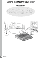
MIXING CONSOLE Owner's Manual Making the Most Of Your Mixer Pages 6 to 18 E - Yamaha 6FX | Owner's Manual - Page 2
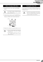
damaged, turn the power switch off, remove the power plug from the AC outlet, and contact your dealer. If you continue using the unit without heeding this instruction, fire or going on vacation, remove the power plug from the AC outlet. Leaving it connected is a potential fire hazard. 2 MG16/6FX - Yamaha 6FX | Owner's Manual - Page 3
1. IMPORTANT NOTICE: DO NOT MODIFY THIS UNIT! This product, when installed as indicated in the instructions contained in this manual, meets FCC requirements. Modifications not expressly approved by Yamaha may void your authority, granted by the FCC, to use the product. 2. IMPORTANT: When connecting - Yamaha 6FX | Owner's Manual - Page 4
. Please read through this Owner's Manual carefully before beginning use, so that you will be able to take full advantage of this mixer's superlative features and enjoy trouble-free operation for years to come. Features G The MG16/6FX provides 16 input channels and mixes the signals into Stereo and - Yamaha 6FX | Owner's Manual - Page 5
adaptor into a standard household power outlet. • Be sure to unplug the adaptor from the outlet when not using the mixer, or when there are lightning storms in the area. • To avoid generating unwanted noise, make sure there is adequate distance between the power adaptor and the mixer. MG16/6FX 5 - Yamaha 6FX | Owner's Manual - Page 6
away you go ... right? Well, if you've done this before you won't have any problems, but if this is the first time you've ever used a mixer you might want to read through this little tutorial and pick up a few basics that will help you get better performance and make better mixes. 6 MG16/6FX - Yamaha 6FX | Owner's Manual - Page 7
of connectors on the back of my mixer?" and "What's the difference?". Let handles, as will the owner's manual (you do keep your manuals in a safe place, don't problem. Microphone cables usually have this type of connector, as do the inputs and outputs of most professional audio gear. Female MG16/6FX - Yamaha 6FX | Owner's Manual - Page 8
well as spurious electromagnetic noise generated by power lines, motors, electric appliances, computer monitors, and a variety of other relatively large, and will be amplified to an alarming degree in the mixer's highgain head amplifier. To summarize: Microphones: Short line-level runs 8 MG16/6FX - Yamaha 6FX | Owner's Manual - Page 9
to match the level of the connected equipment. G Inputs that feature a "Gain" control-such as the mono-channel inputs on your Yamaha mixer-will accept a very wide range of input levels because the control can be used to match the input's sensitivity to the signal. More on this later. MG16/6FX 9 - Yamaha 6FX | Owner's Manual - Page 10
than boost. 10 MG16/6FX 3 Channel Peak LED & Fader The channel peak LED is your most valuable tool for setting the input "gain" control for optimum performance. Note that it is located after the head amp and EQ stage. I Master Section 4 Summing Amplifier This is where the actual "mixing" takes place - Yamaha 6FX | Owner's Manual - Page 11
will only amplify the noise contributed by the preceding stages. Just remember that too much initial gain is bad too, because it will overload our channel circuitry and cause clipping. MG16/6FX 11 - Yamaha 6FX | Owner's Manual - Page 12
of mixer mix to be sure you don't stay in the "peak zone" all the time. If the output level meters are peaking constantly you will need to lower the channel faders until the overall program falls within a good range- and this will depend on the "dynamic range" of your program material. 12 MG16/6FX - Yamaha 6FX | Owner's Manual - Page 13
fed to the external effect unit-a reverb unit, for example-and the output from the effect unit is returned to the AUX Return jack and mixed back into the main program. The send level is affected by the channel fader so the effect level always remains in proportion to the channel signal. MG16/6FX 13 - Yamaha 6FX | Owner's Manual - Page 14
stereo program. Once the mix between the channels assigned to the group is established via the channel faders, the overall level of the entire group can be conveniently adjusted via a single group fader. Channel faders Assigned to Stereo (Controlled Individually) Stereo Master Fader 14 MG16/6FX - Yamaha 6FX | Owner's Manual - Page 15
type of in/out processor. Channel Fader When a plug is inserted into the channel insert jack, the internal signal path is interrupted and sent outside the mixer for external processing. Channel insert jacks must be used with Tip Sleeve Tip To the output jack of the external processor MG16/6FX 15 - Yamaha 6FX | Owner's Manual - Page 16
what instrument or technique is being used to drive the message? That's where the focus of your mix should be. You're using a hightech tool to do the mixing, but the mix itself is as much art as the music. Approach it that way and your mixes will become a vital part of the music. 16 MG16/6FX - Yamaha 6FX | Owner's Manual - Page 17
clear and clean try using cut to remove frequencies that are cluttering up the mix rather than trying to boost the mix into clarity. One of the biggest problems with too much boost is that it adds gain to the signal, increasing noise and potentially overloading the subsequent circuitry. MG16/6FX 17 - Yamaha 6FX | Owner's Manual - Page 18
Effects & EQ Your MG mixer features a high-performance internal effect system and graphic equalizer that offers extraordinary sound-processing power and versatility without the need the response of the overall mix, and for minimizing feedback in live situations. For details see page 22. 18 MG16/6FX - Yamaha 6FX | Owner's Manual - Page 19
below 80 Hz. (But note that regardless of the switch setting, the mixer does not apply this HPF to the line inputs of stereo input chan- nels.) 15 dB Shelving 100 Hz • Stereo channels (CHs 9/10, 11/12, 13/14, 15/16) This four-band equalizer adjusts the channel's high, hi-mid, lo-mid MG16/6FX 19 - Yamaha 6FX | Owner's Manual - Page 20
regardless of the setting of the ST switch 9. B Channel Fader Adjusts the output level of the signal being input to the channel. Use these faders to adjust the volume balance among the various channels. NOTE To reduce noise, set the fader sliders for unused channels all the way down. 20 MG16/6FX - Yamaha 6FX | Owner's Manual - Page 21
of the mixed L/R signal power on and off. If you set the switch on, the mixer supplies power to all channels problem when connecting to balanced dynamic microphones. • To avoid damage to speakers, be sure to turn off amplifiers (or powered speakers) before turning this switch on or off. MG16/6FX - Yamaha 6FX | Owner's Manual - Page 22
channel's PFL output it sent to the C-R OUT jacks, PHONES jacks, and level meter. 2 If the 2TR IN switch is on ( ), the signal supplied POWER Indicator This indicator lights up when the mixer's power 14 VOCAL REVERB 2 15 VOCAL REVERB 3 16 VOCAL REVERB 4 • PARAMETER Control Adjusts the MG16/6FX - Yamaha 6FX | Owner's Manual - Page 23
channel. • The phone-type jacks for CH9/10 and 11/12 also support mixer, or other such device. 5 ST OUT (L, R) Jacks These jacks output the mixed power amplifier driving your main speakers. • XLR jacks XLR-type balanced output jacks. • Phone jacks TRS phone-type balanced output jacks. MG16/6FX 23 - Yamaha 6FX | Owner's Manual - Page 24
These jacks output the mixed signal whose level . A POWER Switch Use this switch to set the mixer power to ON channels) Tip: Hot Sleeve: Ground Sleeve Tip * These jacks will also accept connection to monaural phone plugs. If you use monaural plugs, the connection will be unbalanced. 24 MG16/6FX - Yamaha 6FX | Owner's Manual - Page 25
sure that all devices are turned off. Also be sure that all of the mixer's channel faders and master control faders are set all the way down. (2) For each cassette, video, etc.) Powered Monitor Speakers Master Recorder (MD, CD-R, DAT, etc.) Personal Computer MTR Microphone Headphones MG16/6FX 25 - Yamaha 6FX | Owner's Manual - Page 26
for Live Performance Monitor Speakers (Internal) Drums Power Amp Effector CD, Cassette, or DAT Recorder CD Player Microphones Synthesizer Effector DI Bass Guitar Power Amp Main Speakers (External) 26 MG16/6FX Microphones Headphones Guitar Example of Speaker Arrangement Stage - Yamaha 6FX | Owner's Manual - Page 27
screws. (3) Mount the unit into the rack, and fasten it into place. NOTE If you wish you may move the left support to the right side and the right support to the left side, as shown in the drawing. Do not install the mixer near power amps or other heat-generating devices. Setting Up MG16/6FX 27 - Yamaha 6FX | Owner's Manual - Page 28
Channel Equalization: Max. Variation (CHs 9/10 to 15/16) 3 Graphic Equalizer Internal Digital Effects Monaural/Stereo Input Peak Indicator Level Meters Phantom +48 VDC Power (Balanced input) Included Accessory Power Supply Power at nominal level; all channel mix controls at minimum level. MG16/6FX - Yamaha 6FX | Owner's Manual - Page 29
mV) -10 dBV (316 mV) +10 dBV (3.16 V) RCA pin jack Where 0 dBu = 0.775 V manual are for information purposes only. Yamaha Corp Yamaha dealer. European Models Purchaser/User Information specified in EN55103-1 and EN55103-2. Inrush Current: 6A Conforms to Environments: E1, E2, E3 and E4 MG16/6FX - Yamaha 6FX | Owner's Manual - Page 30
Appendix Dimensional Diagrams 393 H 108 101.3 3 W 423 31.5 428 27.5 309.6 D 416.6 480 When mounted on rack 30 MG16/6FX Unit: mm - Yamaha 6FX | Owner's Manual - Page 31
Block Diagram and Level Diagram Appendix MG16/6FX 31 - Yamaha 6FX | Owner's Manual - Page 32
filial av Yamaha Scandinavia AB Grini Næringspark 1 N-1345 Østerås, Norway Tel: 67 16 77 70 OTHER EUROPEAN COUNTRIES Yamaha Music Central Europe Yamaha Manual Library http://www2.yamaha.co.jp/manual/english/ U.R.G., Pro Audio & Digital Musical Instrument Division, Yamaha Corporation © 2003 Yamaha
-
 1
1 -
 2
2 -
 3
3 -
 4
4 -
 5
5 -
 6
6 -
 7
7 -
8
-
9
-
10
-
11
-
12
-
13
-
14
-
15
-
16
-
17
-
18
-
19
-
20
-
21
-
22
-
23
-
24
-
25
-
26
-
27
-
28
-
29
-
30
-
31
-
32
 |
 |

MIXING CONSOLE
Owner’s Manual
Making the Most Of Your Mixer
Pages 6 to 18
E