Yamaha 6FX Owner's Manual - Page 20
PAN Control CHs 1 to 8, PFL Pre-Fader Listen Switch
 |
View all Yamaha 6FX manuals
Add to My Manuals
Save this manual to your list of manuals |
Page 20 highlights
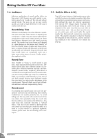
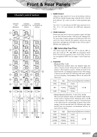
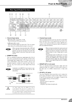
Front & Rear Panels 5 AUX1 and AUX2 Controls The AUX1 knob controls the signal level that the channel sends to the AUX1 bus; the AUX2 knob controls the signal level to the AUX2 bus. These knobs should generally be set close to the position. If you are using stereo channels, the signals from the L (odd) and R (even) channels are mixed and sent to the AUX1 and AUX2 buses. NOTE These controls allow you to output the signal to the AUX buses regardless of the setting of the ST switch 9. 6 PRE Switch Selects whether the pre-fader or the post-fader signal is fed to the AUX2 bus. If you set the switch on ( ), the mixer sends the pre-fader signal-the signal prior to passage though channel fader B-to the AUX2 bus, so that AUX2 output is not affected by the fader. If you set the switch off ( ) the mixer sends the post-fader signal to the AUX2 bus. Note that this switch applies to AUX2 only. The signal to the AUX1 bus always passes through the channel fader first. 7 EFFECT Control Adjusts the level of the signal sent from the channel to the EFFECT bus. Note that the signal level will also vary according to the setting of the channel fader. If you are using stereo channels (CHs 9/10, 11/12, 13/14, 15/16), the signals from the L (odd) and R (even) channels are mixed and then sent to the EFFECT bus. 8 PAN Control (CHs 1 to 8) PAN/BAL Control (9/10 and 11/12) BAL Control (13/14 and 15/16) The PAN control determines the positioning of the channel's signal on the Group 1-2/3-4 buses or on the Stereo L and R buses. The BAL control knob sets the balance between left and right channels. Signals into to the L input (odd channel) feed to the Group 1/3 bus or to the Stereo L bus; signals into the R input (even channel) feed to the Group 2/4 bus or the Stereo R bus. NOTE On channels where this knob provides both PAN and BAL controls (9/10 and 11/12), the knob operates as a PAN control if you are inputting through the MIC jack or into the L (MONO) input only, and operates as a BAL control if you are inputting into both L and R inputs. 9 ST Switch This switch assigns the channel's signal to the Stereo L and R buses. To send the signal to the Stereo bus, set the switch on by pressing it in ( ). The switch lights up orange to indicate that it is on. 0 PFL (Pre-Fader Listen) Switch This switch lets you monitor the channel's pre-fader signal. To set the switch on, press it in ( ) so that it lights up. When the switch is on, the mixer outputs the channel's pre-fader signal to the PHONES and C-R OUT jacks, for monitoring. A GROUP Switches Use these switches to send the channel's signal to the Group 1-2 and/or Group 3-4 buses. Setting the switch on ( ) causes the signal to be sent to the corresponding group buses. NOTE These switches allow you to assign the signal to either or both groups regardless of the setting of the ST switch 9. B Channel Fader Adjusts the output level of the signal being input to the channel. Use these faders to adjust the volume balance among the various channels. NOTE To reduce noise, set the fader sliders for unused channels all the way down. 20 MG16/6FX
-
 1
1 -
2
-
3
-
4
-
5
-
6
-
7
-
8
-
9
-
10
-
11
-
12
-
13
-
14
-
 15
15 -
 16
16 -
 17
17 -
 18
18 -
 19
19 -
 20
20 -
 21
21 -
 22
22 -
 23
23 -
 24
24 -
 25
25 -
26
-
27
-
28
-
29
-
30
-
31
-
32
 |
 |