Yamaha 740 Owner's Manual - Page 1
Yamaha 740 Manual
 |
UPC - 086792879437
View all Yamaha 740 manuals
Add to My Manuals
Save this manual to your list of manuals |
Page 1 highlights
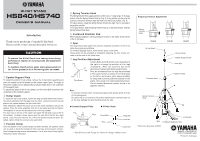
HI-HAT STAND HS840/HS740 OWNER'S MANUAL Introduction Thank you for purchasing a Yamaha Hi-Hat Stand. Please read this owner's manual thoroughly before use. CAUTION • To prevent the Hi-Hat Stand from coming loose during performance, tighten all securing bolts and adjustment bolts firmly. • To maintain smooth action, apply some grease-grade oil (ex. lithium grease) to all of the moving parts as needed. q Cymbal Support Plate To install the bottom hi-hat cymbal, remove the hi-hat clutch assembly and place the cymbal on the felt washer on the cymbal support plate. The angle of the bottom cymbal can be adjusted by turning the angle bolt on the underside of the support plate. To adjust the angle of the hi-hat cymbal, use the Knob Bolt located on the underside of the cymbal support. w Hi-Hat Clutch To install the top hi-hat cymbal, loosen the wing bolt and remove the entire hihat clutch assembly from the upper pull rod. Next, remove the clutch nut and position the cymbal between the two clutch felts. After installation, tighten the clutch nut on to the clutch assembly to secure the cymbal. Place the entire assembly onto the hi hat upper pull rod and tighten the wing bolt to secure the desired position of the top cymbal. The lock nuts on the top of the clutch can adjust the feel and sound of the hi hat cymbals. To obtain a loose sound, open the nuts off of the felt; for a tight sound, close the nuts onto the felt. Once the desired sound has been obtained, tighten firmly the lock nuts onto each other. e Position Clamp Once the bottom hi-hat cymbal height has been decided, the position clamp can be used to mark the settings for future set ups and to prevent unintentional changes during musical performances. Use a drum key to firmly tighten the position clamp into place. r Spring Tension Knob The Spring Tension Knob supplies tension control over a 11-step range, To increase tension, slide the Spring Tension Knob up (Fig. A) to any position you like (use the scale as a reference) and then rotate the knob to the left to lock in place. (Fig. B) To reduce tension, rotate the Spring Tension Knob to the right (Fig. C) and slide to any position you like. To increase tension, slide the Spring Tension Knob up, to decrease tension, slide the Spring Tension Knob down. t Footboard Stabilizer Rod The Footboard stabilizer rod should attach to holes in the frame at the bottom of the hi-hat base. y Spur The large heavy-duty rubber feet prevent unwanted movement of the hi-hat stand during playing conditions. To minimize slippage further, there are two spurs in the frame. These spurs can be extended as needed by adjusting the turn screws provided on either side of the frame base. u Leg Position Adjustment Loosen Bolts A and B shown in the illustration to Leg the right to change the position of the legs (footboard). After the position has been Leg determined, tighten both Bolts A and B firmly. Also, we recommend that the legs be positioned in the same manner as shown in the illustration Leg Foot Board on the left so as to leave some space available for setup and to provide sufficient stability for the stand. (This setup is for right-handed drummers. For left-handed drummers, please set up in an opposite manner.) Note: To maintain smooth action, occasionally apply some grease-grade oil to all of the moving parts. Be careful not to use excessive force when tightening the extender base nut as this may damage the nylon bushing inside the tube. ● Cymbal Support Plate ● Hi-Hat Clutch Felt Cymbal Support Plate Fiber Clutch Bolt Felts Knob Bolt Wing Bolt Lock Nut Clutch Nut * Specifications and design are subject to change without notice. ● Spring Tension Adjustment Spring Tension Knob (Fig.A) Hi-Hat Shaft Extender Base (Fig.B) (Fig.C) Hi-Hat Clutch Cymbal Support Plate Knob Bolt Position Clamp A Spring Tension Knob B Footboard Spur Footboard Stabilizer Rod * This product photograph is HS840. Printed in Indonesia
-
 1
1
 |
 |