Yamaha AV-S7 Owner's Manual - Page 20
Controls And Their Functions, Center Speaker With Control Unit
 |
View all Yamaha AV-S7 manuals
Add to My Manuals
Save this manual to your list of manuals |
Page 20 highlights
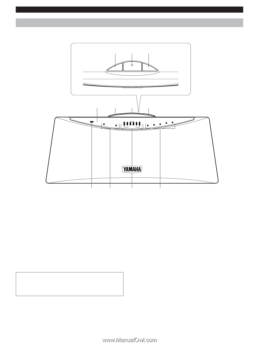
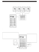
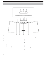
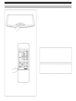
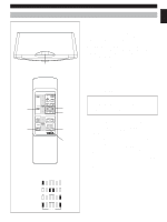
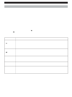
CONTROLS AND THEIR FUNCTIONS CONTROLS AND THEIR FUNCTIONS CENTER SPEAKER (WITH CONTROL UNIT) 123 INPUT STANDBY/ON PROGRAM Remote control sensor 1 2 3 STANDBY INPUT 1 INPUT 2 VOLUME L C R REAR D E A B C 4 5 6 7 1 INPUT selector button This button switches between INPUT 1 and INPUT 2 each time it is pressed. Check the INPUT 1/2 indicator 5 to see which is in use. 2 STANDBY/ON (Switch) button This button switches between power-on and standby each time it is pressed. When standby mode is activated, the STANDBY indicator 4 lights up. When the power-on is activated, the STANDBY indicator 4 is off. You can tell that the power is on since the INPUT 1/2 indicator 5 and other indicators are lit up. D: Sports E: Mono Movie Check the PROGRAM indicator 7 when making the selection. 4 STANDBY indicator This indicator lights up when in standby mode. 5 INPUT 1/2 indicators These indicators light up to show whether INPUT 1 or 2 is selected. 6 VOLUME indicators These indicators light up according to the setting of the VOLUME buttons 9 on the remote control transmitter. Standby mode In this state, this unit consumes a very small quantity of power to receive infrared signals from 7 PROGRAM indicators These indicators light up to show the selected DSP program. the remote control transmitter. 3 PROGRAM selector button Remote control sensor The sensor is a window for receiving the signal from the This button is used for selecting the DSP program. The remote control transmitter. selections cycle through A→B→C→D→E→OFF→A when pressed. A: Dolby Pro Logic Enhanced B: Dolby Pro Logic C: Concert E-16
-
 1
1 -
2
-
3
-
4
-
5
-
6
-
7
-
8
-
9
-
10
-
11
-
12
-
13
-
14
-
 15
15 -
 16
16 -
 17
17 -
 18
18 -
 19
19 -
 20
20 -
 21
21 -
 22
22 -
 23
23 -
 24
24 -
 25
25 -
26
-
27
-
28
-
29
 |
 |