Yamaha AVS-700 AVS-700 OWNERS MANUAL
Yamaha AVS-700 Manual
 |
View all Yamaha AVS-700 manuals
Add to My Manuals
Save this manual to your list of manuals |
Yamaha AVS-700 manual content summary:
- Yamaha AVS-700 | AVS-700 OWNERS MANUAL - Page 1
Thahk you fo sin the YAMAHA AVS 700 AV selector. , r r ,,, r.r fr J. r. ,r / 4 , , ee„ rJ J P." its _z_rr=_3j0 1 . ., rr 46-pir,o, "? 4, '„0, v,-, ,/, 4/ , ' , VA" ' ✓iii: 7,t1:F.,!LE OF CONTENTS Safety instructions Caution 2 Supplied accessories 6 Controls and - Yamaha AVS-700 | AVS-700 OWNERS MANUAL - Page 2
to persons. The exclamation point within an equilateral triangle is intended to alert you to the presence of important operating and maintenance (servicing) instructions in the literature accompanying the appliance. WARNING TO REDUCE THE RISK OF FIRE OR ELECTRIC SHOCK, DO NOT EXPOSE THIS APPLIANCE - Yamaha AVS-700 | AVS-700 OWNERS MANUAL - Page 3
of this AV selector to a minimum level while lowering the tonearm to play a record; turn the volume up with the stylus in the groove. 6. Do not attempt to clean the unit with chemical solvents; this might damage the finish. Use a clean, dry cloth. 7. Be sure to read the "troubleshooting" section on - Yamaha AVS-700 | AVS-700 OWNERS MANUAL - Page 4
3 Remote ccntrol Transmitter Batteries (size "AAA", R03) 0 Video Cord Audio Cord - Yamaha AVS-700 | AVS-700 OWNERS MANUAL - Page 5
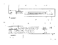
®© 0 IONIA NATURAL SOUND AV SELECTOR AVG-700 POWER AUX STANDBY „,.. LA.?) 8 VIDEO !Rout& A lac OUT I - O O VCR 8 Van 1 O 0 a O O O MONO L0 DOS/TV TAP88 TAPS 1 TONGA CO MOND ..ROPI O sI INPUTEELECTOR REC OUT P. DOWN - Yamaha AVS-700 | AVS-700 OWNERS MANUAL - Page 6
18 19 POWER TUNER CO RI4ONO ED [2:3 El Coe/TV TAPE 2 TAPE 1 E3 CD El • VCR 2 VCR 1 LC EDI CD INPUT El AUX [ 71 . ,-j L I -20dB DOWNATT. UP ELI 21 NMI R CONTROL FIE TRANSMITTER 5 ec) GC REMOTE CONTROL sensor 3o r.= Within 7 meters (23 feet) - Yamaha AVS-700 | AVS-700 OWNERS MANUAL - Page 7
be recorded. The REC OUT ON/OFF button Is used to turn on/off the output of the source signal selected with the REC OUT selector through the REC OUT jacks. They enable video/audio recording of any source, even while monitoring another. For details, see the "RECORDING" section described later - Yamaha AVS-700 | AVS-700 OWNERS MANUAL - Page 8
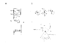
lights. IM REAR PANEL (See Fig. Ell 0 REMOTE CONTROL cable connectors These connectors are used to connect compatible YAMAHA components (with an m$ Egi mark) to your AV selector for remote control of each component. The cables for each component are supplied with this unit. PHONO -- Connect to - Yamaha AVS-700 | AVS-700 OWNERS MANUAL - Page 9
THE REMOTE CONTROLTN!.NSMITTER (See Fig. 11.) If the CD, LD/CDV player, tuner, turntable and cassette deck connected to your AV selector are YAMAHA components designed for remote control compatibility (components with an zfivw mark), then the remote control transmitter supplied with the DSP-A700 - Yamaha AVS-700 | AVS-700 OWNERS MANUAL - Page 10
off all electrolyte residue from the battery compartment. Replace with new batteries. • OPERATION RANGE (See Fig. ) You must point the remote control unit toward the AV selector and be within about 7 meters (23 feet) of it for proper operation. 9 - Yamaha AVS-700 | AVS-700 OWNERS MANUAL - Page 11
, CONNECTI9NS System Connection Diagram 5 gam a MAIM Tape deck LINE IN r i= imnrt LINE OUT * Remota terminal for a tape deck with an !RID mark Tuner Output MEM/ • Remote terminal for e. tuner with an Egge mark TV set Laser Vision Disc player or CD Video player VCR Video output jack - Yamaha AVS-700 | AVS-700 OWNERS MANUAL - Page 12
components. Notes on REMOTE CONTROL terminals The REMOTE CONTROL terminals are used when you have YAMAHA compatible components bearing the ma mark. If your AV selector is used with the YAMAHA DSP-A700 amplifier, the remote control transmitter supplied with the amplifier can directly control this - Yamaha AVS-700 | AVS-700 OWNERS MANUAL - Page 13
VIDEO COMPONENTS ® TV SET Connect the video output jack from the TV set to the TV VIDEO SIGNAL jack on the rear panel of this unit and connect the audio output jacks from the TV set to the TV AUDIO SIGNAL jacks. ■ LASER VISION DISC PLAYER/CDV PLAYER Connect the video output jack from the laser - Yamaha AVS-700 | AVS-700 OWNERS MANUAL - Page 14
power cord of your tuner, cassette deck or other component to one of the two SWITCHED AC OUTLETS to automatically turn it on when the AV selector is turned on. The maximum total power consumption of the components connected to the SWITCHED AC OUTLETS must not exceed 300 watts. 2. Connect the power - Yamaha AVS-700 | AVS-700 OWNERS MANUAL - Page 15
is not listed in the SYMPTOM column, disconnect the power cord and contact your dealer or service center for help. lSYMP7OM The amplifier fails to turn on when the POWER switch is not turned on. • Connect cord properly. If the problem persists, the cables may be defective. to Set the amplifier - Yamaha AVS-700 | AVS-700 OWNERS MANUAL - Page 16
DES CAMPANULES, LOGNES 77321 MARNE LA VALLEE CEDEX 2. FRANCE YAMAHA ELECTRONICS (UK) LTD. YAMAHA HOUSE, 200 RICKMANSWORIH ROAD WATFORD, HERTS WD1 7JS, ENGLAND YAMAHA SCANDINAVIA A.B. J A WETTERGRENS GATA 1, BOX 30053, 400 43 VASTRA FROLUNDA, SWEDEN YAMAHA MUSIC AUSTRALIA PTY, LTD. 17.33 MARKET ST
-
 1
1 -
 2
2 -
 3
3 -
 4
4 -
 5
5 -
 6
6 -
 7
7 -
8
-
9
-
10
-
11
-
12
-
13
-
14
-
15
-
16
 |
 |
VS 700
Natural
Sound
AV
Selector
i
10
Audio/5
Video
Inputs,
Including
4
S
Video
Terminals
4
Audio/2
Video
Rec
Out
Terminals
Ideally
suited
or
use
with
the
DSP-A700
Digital
Sound
Field
Processing
Amplifier
-20
dB
Audio
Muting
Wireless
Remote
Control
Transmitter
Thahk
you
fo
sin
the
YAMAHA
AVS
700
AV
selector
.
r=3
_
z
_
r
_j
0
1
4
6
.
rr
-p
ir,o,
4
,
.,
"?
,
'
V
A
"
'
,,,
r
r
r.r
fr
J.
r.
,
'„,
0v,-
,
,/,
4/
,
,r
/
4
,
,
ee„
rJ
J
P."
7,t1:F.,!LE
OF
CONTENTS
Safety
instructions
Caution
Supplied
accessories
..
.
...
.
...
..
.
..
...
.......
....
.
....
.
..
.
...
.
Controls
and
Their
functions.
..
.
..
...
..
..
.
.
.
•
6
Using
the
remote
control
transmitter
.
..
,
.............
.
.
..............
8
Connections
10
Basic
operat
on
13
Troubleshooting
14
Specifications
Back
cover
its
✓iii:
-
,
-
2
IMPORTANT
6
Please
record
the
serial
number
of
your
unit
in
the
space
below.
Model:
AVS-100
Serial
No.:
The
serial
number
is
located
on
the
rear
of
the
unit.
Retain
this
Owner's
Manual
in
a
safe
place
for
future
reference.