Yamaha AX 596 MCXSP10 Manual - Page 11
Connections - amplifier manual
 |
View all Yamaha AX 596 manuals
Add to My Manuals
Save this manual to your list of manuals |
Page 11 highlights
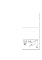
English CONNECTIONS Caution: Plug in this unit and other components after all connections are completed. ● All connections must be correct, that is to say L (left) to L, R (right) to R, "+" to "+" and "-" to "-". Also refer to the owner's manual for each of your components. ● Use RCA type pin plug cables for audio/video units except speakers. ● The output (or input) terminals of YAMAHA audio/video units numbered 1, 2, 3, 4, etc. on the rear panel must be connected to the same-numbered terminals of this unit. Turntable Tuner Tape deck, etc. Speakers A GND OUTPUT OUTPUT LINE OUT LINE IN Right Left *1 GND PHONO R L 1 CD/DVD R L AUDIO SIGNAL R L 2 TUNER 3 IN (PLAY) TAPE 4 OUT (REC) 3 IN (PLAY) MD 4 OUT (REC) AUX COUPLER R L PRE OUT MAIN IN 2 * R R L B SPEAKERS L A CAUTION SEE INSTRUCTION MANUAL FOR CORRECT SETTING. IMPEDANCE SELECTOR SET BEFORE POWER ON A OR B : 4ΩMIN. /SPEAKER A OR B : 6ΩMIN. /SPEAKER A B : 8ΩMIN. /SPEAKER A B : I2ΩMIN. /SPEAKER (U.S.A. model) MAINS AC OUTLETS SWITCHED I20V 60Hz l00W MAX. TOTAL Right * * 3 4 To AC outlet Left AUDIO OUT AUDIO OUT LINE IN LINE OUT CD player or DVD player Video cassette player, etc. MD recorder, etc. Speakers B 1234 Refer to page 9 for descriptions. : Indicates the direction of signals. PHONO R L 3 IN (PLAY) TAPE 4 OUT (REC) Note These terminals are for connecting a turntable with an MM or high output MC cartridge. If you have a turntable with a low output MC cartridge, use an inline boosting transformer or MC-head amplifier when connecting to these terminals. E-7
-
 1
1 -
2
-
3
-
4
-
5
-
 6
6 -
 7
7 -
 8
8 -
 9
9 -
 10
10 -
 11
11 -
 12
12 -
 13
13 -
 14
14 -
 15
15 -
 16
16 -
17
-
18
-
19
 |
 |
