Yamaha CLP-110 Owner's Manual - Page 29
Keyboard Stand Assembly
 |
View all Yamaha CLP-110 manuals
Add to My Manuals
Save this manual to your list of manuals |
Page 29 highlights
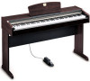
ENGLISH Keyboard Stand Assembly CAUTION Be careful not to confuse parts, and be sure to install all parts in the correct direction. Please assemble in accordance with the sequence given below. • Assembly should be carried out by at least two persons. • Be sure to use the correct screw size, as indicated below. Use of incorrect screws can cause damage. • Be sure to tighten up all screws upon completing assembly of each unit. • To disassemble, reverse the assembly sequence given below. Have a Phillips-head (+) screwdriver ready Remove the following parts from the package. Assembly Parts 6 × 16 mm flat-head screws ×8 AC power cord Damper pedal Cord holders ×2 2. Install the main unit (A). CAUTION • Fingers can become pinched between the main unit and the rear or side panels, be extra careful so as not to drop the main unit. • Do not hold the keyboard in any position other than the position shown in the illustration. Place the main unit (A) on the side panels (C) with the screws on its bottom panel (toward the rear of the main unit) just behind the grooves in the brackets located at the top of the side panels. Then slide the main unit forward until it stops. Align the holes in the bottom panel of the main unit with the holes in the brackets on the side panels. (Center the main unit to produce equal clearance on the left and right sides, as shown in the illustration.) Then use the four 6 × 16 mm flat-head screws to attach the main unit. Two screws can be attached from the front side and two screws from the rear. A C C B 1. Attach the center panel (B) to the side panels (C). The center panel (B) is installed between the side panels (C). The brackets on each end of the center panel should face the rear of the stand assembly. Place the square holes in the center-panel brackets over the lugs extending from the side panels, then slide down the center panel. Each side of the center panel is attached using two 6 × 16 mm flat-head screws. 10 cm A 10 cm A 6 x 16 mm flat-head screw C Be sure to place your hands at least 10 cm from either end of the main unit when positioning it. A C B C NOTE If the holes of the front side brackets are not aligned with the screw hole, position the sides of the side panels so that they are parallel with the side of the unit. 6 x 16 mm flat-head screw CLP-110 Keyboard Stand Assembly 29
-
 1
1 -
2
-
3
-
4
-
5
-
6
-
7
-
8
-
9
-
10
-
11
-
12
-
13
-
14
-
15
-
16
-
17
-
18
-
19
-
20
-
21
-
22
-
23
-
 24
24 -
 25
25 -
 26
26 -
 27
27 -
 28
28 -
 29
29 -
 30
30 -
 31
31 -
 32
32 -
 33
33 -
 34
34 -
35
-
36
-
37
-
38
-
39
-
40
-
41
-
42
-
43
-
44
-
45
-
46
 |
 |
