Yamaha CP2000 Owner's Manual
Yamaha CP2000 Manual
 |
View all Yamaha CP2000 manuals
Add to My Manuals
Save this manual to your list of manuals |
Yamaha CP2000 manual content summary:
- Yamaha CP2000 | Owner's Manual - Page 1
POWER AMPLIFIER Owner's Manual POWER TEMP PROTECTION POWER ON OFF POWER AMPLIFIER 20 15 L CLIP R 20 15 25 10 25 10 30 LEVEL 30 6 6 40 3 40 3 0 L -dB 0 R Keep This Manual For Future Reference. E - Yamaha CP2000 | Owner's Manual - Page 2
coloured BLUE must be connected to the terminal which is marked with the letter N or coloured BLACK. The wire which is coloured BROWN must be connected to the terminal which is marked with the letter L or coloured RED. * This applies only to products distributed by YAMAHA KEMBLE MUSIC (U.K.) LTD. - Yamaha CP2000 | Owner's Manual - Page 3
be dropped or the cabinet be damaged, turn the power switch off, remove the power plug from the AC outlet, and contact your dealer. If you continue using the unit without heeding this instruction, fire or electrical shock may result. • If the power cord is damaged (i.e., cut or a bare wire is exposed - Yamaha CP2000 | Owner's Manual - Page 4
the CP2000 7 Installation 7 Connecting Inputs 7 Connecting Speakers 9 Connecting S115 and S112 loudspeakers 11 Turning On the Power 11 Protection System 11 Daisy Chaining Inputs 12 Troubleshooting 13 Appendix 14 Specifications 14 Dimensions 15 Block Diagram 16 CP2000-Owner's Manual - Yamaha CP2000 | Owner's Manual - Page 5
high-power, superb sonic performance, and reliability, all backed by the Yamaha tradition of excellence in professional audio. CP2000 key features include • 650 W+650 W into 4Ω stereo, 450 W+450 W into 8Ω stereo. • 2,000 W into 4Ω bridged, 1,300 W into 8Ω bridged. • Yamaha Speaker Processing matches - Yamaha CP2000 | Owner's Manual - Page 6
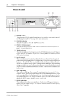
Power" on page 11 for more information. B POWER indicator This indicator lights up when the CP2000 is turned on. C PROTECTION indicator This indicator shows the status a channel's output signal does clip, that channel's limiter circuit is activated to prevent further signal distortion. It's okay for - Yamaha CP2000 | Owner's Manual - Page 7
STEREO BRIDGE PARALLEL OFF ON CHANNEL L (BRIDGE) NEUTRIK 2 1 3 YAMAHA SPEAKER PROCESSING 23 2 1 1 2 CHANNEL R (-) BRIDGE (+) SPEAKERS CHANNEL L 5 A INPUTs The inputs for each CP2000 STEREO, PARALLEL, or BRIDGE. STEREO-In this mode, which is typically used to amplify stereo to form a - Yamaha CP2000 | Owner's Manual - Page 8
CP2000 will be grounded adequately via the power amplify stereo sources. The following hookup example shows how the CP2000 can be used in STEREO mode. STEREO BRIDGE PARALLEL CHANNEL R 2 1 3 INPUT STEREO BRIDGE PARALLEL OFF ON CHANNEL L (BRIDGE) NEUTRIK 2 1 3 YAMAHA SPEAKER PROCESSING - Yamaha CP2000 | Owner's Manual - Page 9
how the CP2000 can be used in PARALLEL mode. STEREO BRIDGE PARALLEL CHANNEL R 2 1 3 INPUT STEREO BRIDGE PARALLEL OFF ON CHANNEL L (BRIDGE) NEUTRIK 2 1 3 YAMAHA SPEAKER PROCESSING MONO OUT . • Speakers can be connected to the 1/4" phone jacks and 5-way binding posts. CP2000-Owner's Manual - Yamaha CP2000 | Owner's Manual - Page 10
The following hookup example shows how the CP2000 can be used in BRIDGE mode. STEREO BRIDGE PARALLEL CHANNEL R 2 1 3 INPUT STEREO BRIDGE PARALLEL OFF ON CHANNEL L (BRIDGE) NEUTRIK 2 1 3 YAMAHA SPEAKER PROCESSING 2 1 1 2 CHANNEL R (-) BRIDGE (+) SPEAKERS CHANNEL L Total impedance - Yamaha CP2000 | Owner's Manual - Page 11
front-panel rack-mounting holes, the CP2000 also features support brackets at the rear, which offer additional support and should be fixed to the rear of the rack. The CP2000 can also be placed horizontally on be wired as follows. Male XLR plug 1 (ground) 3 (cold) 2 (hot) CP2000-Owner's Manual - Yamaha CP2000 | Owner's Manual - Page 12
, LEVEL controls, and signal and CLIP indicators are active in each CP2000 mode. Channel R L Item INPUT connectors LEVEL control Signal & CLIP indicators INPUT connectors LEVEL control Signal & CLIP indicators STEREO O O O O O O PARALLEL X O O O O O BRIDGE X X O O O O CP2000-Owner's Manual - Yamaha CP2000 | Owner's Manual - Page 13
must be connected to the binding post labelled (-). Caution for Speaker Connection 1 Turn off the POWER switch. 2 Before connecting any speakers, remove the protective cover by unscrewing the two fixing screws a way that the connection can be made simply and without problem. CP2000-Owner's Manual - Yamaha CP2000 | Owner's Manual - Page 14
it's important that the total impedance is not less than the minimum specified. In STEREO and PARALLEL modes, the minimum impedance is 2Ω, and for BRIDGE mode it's 4Ω. When 8Ω 8Ω 4Ω 8Ω 8Ω See the "Hookup Examples" on page 4 for more information on connecting speakers. CP2000-Owner's Manual - Yamaha CP2000 | Owner's Manual - Page 15
make sure the YAMAHA SPEAKER PROCESSING switch is set to OFF. Turning On the Power To prevent audible thumps and clicks, turn on your audio equipment in the POWER following order (reverse this order when turning off your equipment)-sound sources, mixer, CP2000. 1 Press the [POWER] switch to turn - Yamaha CP2000 | Owner's Manual - Page 16
L (BRIDGE) NEUTRIK 2 1 3 YAMAHA SPEAKER PROCESSING 2 1 1 2 CHANNEL R (-) BRIDGE (+) SPEAKERS CHANNEL L CHANNEL R 2 1 3 INPUT STEREO BRIDGE PARALLEL OFF ON CHANNEL L (BRIDGE) NEUTRIK 2 1 3 YAMAHA SPEAKER PROCESSING ST OUT Mixer CP2000-Owner's Manual 2 1 1 2 CHANNEL - Yamaha CP2000 | Owner's Manual - Page 17
Yamaha dealer or service center. The heatsink temperature warning circuit activates. The protection circuit activates, opening the output relay and disconnecting the speakers. The output relay closes automatically when the heatsink has cooled down, or the DC fault is removed. CP2000-Owner's Manual - Yamaha CP2000 | Owner's Manual - Page 18
, 1 kHz ≤ -70 dB 104 dB ≥200 +4 dB 33.8 dB 30 kΩ (balanced), 15 kΩ (unbalanced) POWER switch (push on/push off) LEVEL attenuator (31 position) x2 Mode switch (STEREO/BRIDGE/PARALLEL) YAMAHA SPEAKER PROCESSING switch (ON/OFF) XLR-3-31 type (balanced) L+R 1/4" phone jack (balanced) L+R 1/4" phone jack - Yamaha CP2000 | Owner's Manual - Page 19
Circuit Fan Circuit Limiter Circuit Power requirements Idle Power Consumption 1/8 Power Consumption (4Ω) Maximum Power Consumption (4Ω) Dimensions (W × H × D) Weight AC Power cord length 0 dB=0.775 V rms, half power=1/2 power output level POWER subject to change without notice. For European Model - Yamaha CP2000 | Owner's Manual - Page 20
• ON • OFF INV YAMAHA SPEAKER PROCESSING BA CHANNEL ATT R PARALLEL BRIDGE • ON • OFF STEREO POWER POWER CIRCUIT POWER SW Limiter Lch Power Amp CLIP Temperature Sensor (Heat Sink) Protection Circuit CLIP SIGNAL PROTECTION TEMP SIGNAL Limiter Rch Power Amp +B E -B +24 E -24 FAN
-
 1
1 -
 2
2 -
 3
3 -
 4
4 -
 5
5 -
 6
6 -
 7
7 -
8
-
9
-
10
-
11
-
12
-
13
-
14
-
15
-
16
-
17
-
18
-
19
-
20
 |
 |

POWER AMPLIFIER
Owner’s Manual
E
POWER
ON
OFF
TEMP
PROTECTION
POWER
POWER AMPLIFIER
–dB
LEVEL
CLIP
L
L
R
0
3
6
10
15
20
25
30
30
40
R
0
3
6
10
15
20
25
40
Keep This Manual For Future Reference.