Yamaha CP2000 Owner's Manual - Page 12
The following table shows which inputs, LEVEL controls, and signal and CLIP indica
 |
View all Yamaha CP2000 manuals
Add to My Manuals
Save this manual to your list of manuals |
Page 12 highlights
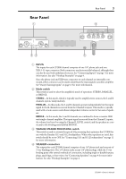
8 Chapter 3-Using the CP2000 To connect an unbalanced source to an INPUT XLR, connect pin 3 (cold) to pin 1 (ground), as shown below. Male XLR plug 1 (ground) 3 (cold) 2 (hot) The following table shows which inputs, LEVEL controls, and signal and CLIP indicators are active in each CP2000 mode. Channel R L Item INPUT connectors LEVEL control Signal & CLIP indicators INPUT connectors LEVEL control Signal & CLIP indicators STEREO O O O O O O PARALLEL X O O O O O BRIDGE X X O O O O CP2000-Owner's Manual
-
 1
1 -
2
-
3
-
4
-
5
-
6
-
 7
7 -
 8
8 -
 9
9 -
 10
10 -
 11
11 -
 12
12 -
 13
13 -
 14
14 -
 15
15 -
 16
16 -
 17
17 -
18
-
19
-
20
 |
 |
8
Chapter 3
—
Using the CP2000
CP2000
—
Owner
’
s Manual
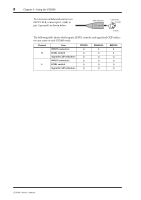
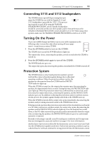
To connect an unbalanced source to an
INPUT XLR, connect pin 3 (cold) to
pin 1 (ground), as shown below.
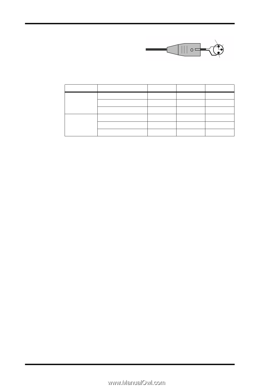
The following table shows which inputs, LEVEL controls, and signal and CLIP indica-
tors are active in each CP2000 mode.
Channel
Item
STEREO
PARALLEL
BRIDGE
R
INPUT connectors
O
X
X
LEVEL control
O
O
X
Signal & CLIP indicators
O
O
O
L
INPUT connectors
O
O
O
LEVEL control
O
O
O
Signal & CLIP indicators
O
O
O
Male XLR plug
1 (ground)
3 (cold)
2 (hot)