Yamaha DXS12mkII DXS18/DXS15mkII/DXS12mkII Owners Manual - Page 1
Yamaha DXS12mkII Manual
 |
View all Yamaha DXS12mkII manuals
Add to My Manuals
Save this manual to your list of manuals |
Page 1 highlights
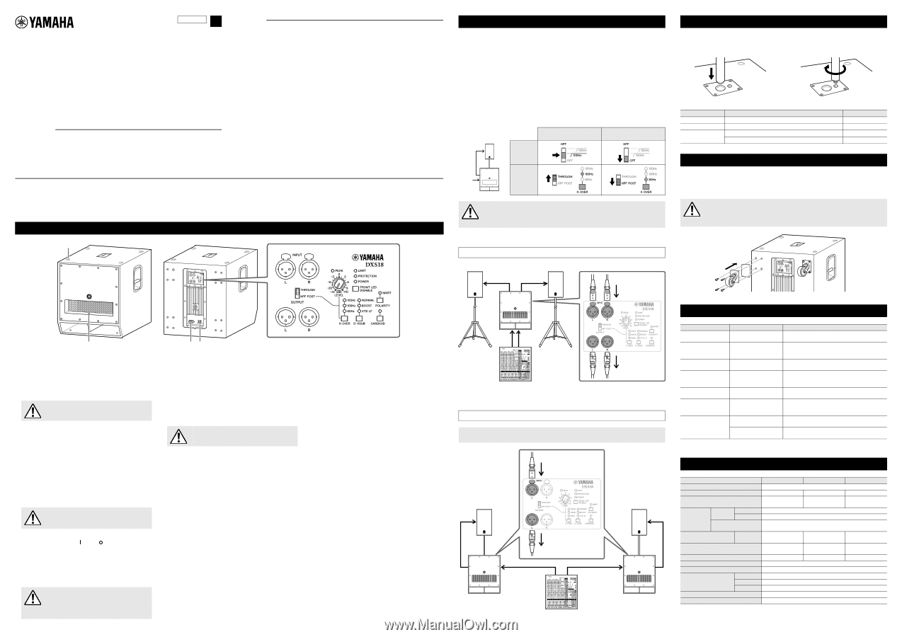
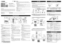
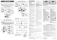
ZZ20050 EN POWERED SUBWOOFER DXS18 DXS15 mkll DXS12 mkll Owner's Manual • The DXS18 is mainly used for the explanations in this manual. • The illustrations as shown in this manual are for instructional purposes only. • The company names and product names used in this manual are the trademarks or registered trademarks of their respective companies. Introduction Thank you very much for purchasing the DXS Powered Subwoofer. The DXS is a powered subwoofer used for sound reinforcement and temporary installations. This owner's manual explains how to set up and use the subwoofer in live venues and temporary PA installations to enhance low-end sound. Be sure to read this manual before using this subwoofer, in order to make sufficient use of the many functions that this product offers. Also, be sure to keep this manual after you are finished reading it. Features High power, high sound pressure, superior low-end playback capabilities Adopting a bandpass type enclusure for high sound pressure. The DXS features a high-resistance input, low distortion woofer and a 1,020 W power amplifier to achieve superior low-end playback capability and high sound pressure. Flexible features • D-XSUB: D-XSUB is a DSP technology that gives users additional dynamic control of the frequency range to meet the demands of a variety of applications or musical styles. • Selectable X-OVER (80/100/120 Hz): Selecting the cut-off frequency and LPF/HPF settings offers users more flexibility to adapt to various applications. • Cardioid mode: The Cardioid mode setting adds additional control of low frequencies for sub-woofer arrays of two or more DXS speakers, effectively reducing the SPL of bass directed towards the stage while increasing the bass levels directed towards the audience. Reliability A high-performance DSP control protects the speaker and amplifier. The DXS can be used worry-free, even under harsh operating conditions. Durability The DXS's sturdy plywood cabinet is covered with an extremely durable polyurea finish that provides added protection from outside elements. Fast and easy setup M20 and Ø35 mm dual pole sockets allow for more flexible set up, while optional casters are also available for improved portability. Included accessories • AC power cord • Owner's manual (this leaflet) • Technical Specifications Optional accessories • Speaker cover: SPCVR-18S01 (for DXS18), SPCVR-DXS152 (for DXS15mkII), SPCVR-DXS122 (for DXS12mkII) • Wheels: SPW-1; 4 pieces w q Controls and functions u r o !0 !1 !6 !7 !8 !9 !5 !2 !3 !4 i e ty q Pole sockets Adapts to commercially available speaker poles of 35 mm diameter and M20 screws. For details on installing speaker poles, refer to "Installing a Speaker Pole." w Feet cups When stacking multiple DXS units, align the rubber feet of the upper DXS unit to the feet cups of the lower. CAUTION Do not stack more than two DXS units. e Front LED Turns on when the power is on. Lights more brightly when the output limiter is active. Using FRONT LED DISABLE switch (!9) allows you to defeat the front LED altogether. r Wheel mounting holes Optional SPW-1 wheels can be installed at these locations. For details on installing the wheels or special precautions you should take, please refer to the relevant manual for the wheels. t AC IN inlet (V-Lock) Connect the AC power cord included with the unit. The AC power cord includes a locking mechanism with a latch. First connect the DXS to the AC power cord, and then connect the power cord to the AC outlet. When removing the cord, push the latch while pulling the cord out. CAUTION Turn off the power before you connect or disconnect the power cord. y Power switch Turns the power to the unit on ( ) or off ( ). If you are using multiple units, turn on the power to each unit one by one. If you turn on the power to multiple units simultaneously, a temporary drop in the power voltage may occur, possibly resulting in abnormal operation of the units. Also, rapidly turning the unit on and off in succession can cause it to malfunction. After turning the unit off, wait for about 5 seconds before turning it on again. CAUTION A slight electrical current will flow even when the power switch is turned off. Make sure to unplug the power cord from the power outlet when not using the speaker for an extended period of time. 1 u INPUT jacks These are balanced input XLR jacks (line-level), and this device outputs the mixed signals of L and R. i OUTPUT jacks These are balanced output XLR jacks for connecting full-range speakers or additional DXS units. The output signal can be switched via the THROUGH/HPF POST switch (o). L/R output from the OUTPUT jacks correspond to L/R input to the INPUT jacks. The mixed signal of L/R is not output. o THROUGH/HPF POST switch Switches the signals output from the OUTPUT jacks (i). CAUTION Make sure to lower the input level when switching. • THROUGH: Outputs unaffected signals from INPUT jacks (u). Select when using HPF of the connected speaker or connecting additional DXS units. • HPF POST: Outputs signal input from INPUT jacks (u) after passing through a HPF. The cutoff frequency of the high pass filter is the frequency specified with the X-OVER switch (!2). Because the output level from the OUTPUT jacks is linked to the LEVEL control (!)1 , the levels of this unit and the full-range speaker change simultaneously. !0 PEAK indicator Lights red when the input level reaches 3 dB below clipping. If the indicator lights frequently, adjust the volume of the input source or lower the LEVEL control (!)1 so that the indicator flashes only briefly at the highest input levels. !1 LEVEL control Adjusts the output level. !2 X-OVER switch Specifies the crossover frequency at 120 Hz, 100 Hz, or 80 Hz. The output from the unit is processed through a low pass filter to cut the range of the selected frequency or higher. When setting THROUGH/HPF POST switch (o) to [HPF POST], the output signals from the OUTPUT jacks are processed through a high pass filter to cut the range of the selected frequency or lower, and the crossover frequency is linked to that of the connected speaker. !3 D-XSUB switch Switches the low-range frequency response characteristics. • NORMAL: A generic setting corresponding to various applications. • BOOST: Boosts the frequency range enhancing and providing punch to the sound. • XTD LF (eXTenDed LF): Extends the bottom of the low frequency range. !4 CARDIOID switch Connection of multiple DXS units enables the use of Cardioid mode. For details on Cardioid mode and using the switch, refer to "Setup of Cardioid Mode" on the opposite page. !5 POLARITY switch Switches the polarity of the unit, normal or inverted. When the polarity is inverted, the INVRT indicator lights. In most cases, this should be set to normal; however, the inverted setting may improve low-range response, depending on the type and location of the speaker system. Select a setting that produces the best low-end sound. !6 LIMIT indicator Lights when the output limiter is active. The output limiter operates in order to protect the speaker and amplifier, attenuating the output signal to the amplifier. If the indicator lights frequently, adjust the volume of the input source or lower the LEVEL control (!)1 so that the indicator only occasionally lights at the highest input levels. !7 PROTECTION indicator Lights when the protection system is active. The protection system operates and the speaker output is muted in the following situations. • If amplifier overheating is detected. • If overcurrent is detected. • Immediately after turning the power on. (The protection system is activated to prevent noise and the indicator lights for about two seconds. The indicator turns off when the power supply has started normally.) !8 POWER indicator Lights when the power is on. !9 FRONT LED DISABLE switch Turns the FRONT LED at the front of the unit on or off. The LED lights when this switch is set to off. Turn this switch on to disable the LED. Basic Setup Input the output signal from a source, such as a mixer, to the INPUT jack of the DXS, and input the output signal from the OUTPUT jack of the DXS to the input jack of a full-range speaker. • X-OVER switch (!2) It is recommended that you match the crossover frequency (the cutoff frequency of the low pass filter) of the DXS and the cutoff frequency of the high pass filter of the full-range speaker. The same frequency range output from the DXS and the full-range speaker may cause interference with each other and degrade the frequency characteristics. • THROUGH/HPF POST switch (o) If the full-range speaker is properly equipped with a high pass filter, you should set this to [THROUGH]. The [THROUGH] setting enables you to control the level independently and minimize signal delay. If the full-range speaker is not equipped with a high pass filter or the high pass filter in the full-range speaker cannot be set to the same cutoff frequency as that of the low pass filter of the DXS, set this to [HPF POST] to use the high pass filter in the DXS. Full-range speaker Combination and setting examples Using the high pass filter in the connected full-range speaker Using the high pass filter in the DXS Full-range speaker From mixer DXS o !2 o !2 CAUTION If multiple powered speakers are connected in daisy-chain fashion, turn each device on in sequence starting from the one nearest to the sound source, and turn them off starting from the one farthest from the sound source. Combination of monaural DXS and stereo full-range speakers Full-range speaker Full-range speaker From mixer DXS Mixer To full-range speaker Combination of stereo DXS and stereo full-range speakers NOTE The L and R jacks are interchangeable; there is no difference in behavior between them. From mixer Full-range speaker Full-range speaker To full-range speaker DXS Mixer DXS Installing a Speaker Pole This is a pole socket used to mount a full-range speaker atop the DXS. The pole socket is compatible with 35 mm or M20 speaker poles, available commercially. When using the pole socket, be sure that the following conditions are met. Ø35 M20 screw Subwoofer DXS18 DXS15mkII DXS12mkII Top-mounted speaker Weight 28.0 kg or less, height 76 cm or less (DSR115) Weight 19.3 kg or less, height 61 cm or less (DXR12) Weight 14.6 kg or less, height 51 cm or less (DXR10) Weight 13.5 kg or less, height 46 cm or less (DXR8) Pole length 120 cm or less 100 cm or less 82 cm or less 90 cm or less Installing Wheels Installing optional wheels SPW-1 at the back of the DXS enables you to transport the unit easily. To install the wheels, use the screws already installed in the DXS unit. Please do not use the speaker once the screws are removed. This causes air leaks to occur in enclosure, resulting in undesirable performance. CAUTION • For details on installing the wheels or special precautions you should take, please refer to the relevant manual for the wheels. • Do not install wheels other than the SPW-1. Troubleshooting Symptom Power does not turn on. Power suddenly turned off. No sound. Sound is interrupted suddenly. Sound howls (feedback). The sound from each speaker differs (if multiple speakers are used.) Sound is distorted. Possible causes Possible solution The power cord is not connected properly. Connect the power cord properly. The protection system has been activated, shutting down the power supply. Turn off the power, wait until the amplifier cools down, and then turn on again. The cable is not connected properly. Connect the cable to the INPUT jack properly. The protection circuit has Wait until the amplifier cools down. If the unit doesn't been activated, muting the automatically reset itself, turn off the power, and then output. on again. A microphone is directed Keep the speaker away from the area where the toward the speaker. microphone picks up the sound. The settings for each speaker differ. Set each switch of each speaker to the same position. Input volume is excessive. Lower the volume of the input device so that the PEAK indicator lights only occasionally. Output volume is exces- Lower the output level with the LEVEL control so that sive. the LIMIT indicator lights only occasionally. * If any specific problem should persist, please contact your Yamaha dealer. General Specifications General Specifications DXS18 DXS15mkII DXS12mkII System Type Powered subwoofer, band-pass type Frequency Range (-10 dB) 32 Hz-120 Hz 40 Hz-150 Hz 42 Hz-150 Hz Measured Maximum SPL (Peak) Pink Noise @1m 136 dB SPL 135 dB SPL 134 dB SPL Power Amplifier Power Dynamic Rating Continuous Power Consumption (1/8 output power) 1,020 W 800 W 100 W Components LF 18" cone, 4" voice coil 15" cone, 2.5" voice coil 12" cone, 2.5" voice coil Dimensions (W × H × D; including rubber feet) 563 × 683 × 721 mm 480 × 611 × 614 mm 400 × 567 × 570 mm Weight 49.7 kg 36.0 kg 30.0 kg Handles Steel, side × 2 Pole Sockets (top surface) Ø35 mm (depth: 80 mm), M20 (threaded depth: 25 mm) Input XLR3-31 × 2 Connectors Output XLR3-32 × 2 (THROUGH or HPF POST) Power IEC AC inlet × 1 (V-Lock) Input Sensitivity (LEVEL: center) +10 dBu Maximum Input Level +24 dBu * The contents of this manual apply to the latest specifications as of the publishing date. To obtain the latest manual, access the Yamaha website then download the manual file.
-
 1
1 -
 2
2
 |
 |