Yamaha EMX212S Owner's Manual - Page 25
POWER PHANTOM switch, LIMITER lamps, POWER AMP switch, YS Processing switch, STAND-BY switch - subwoofer
 |
UPC - 086792831312
View all Yamaha EMX212S manuals
Add to My Manuals
Save this manual to your list of manuals |
Page 25 highlights
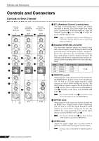
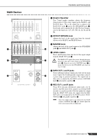
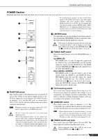
Controls and Connectors POWER Section P Q R S T U P PHANTOM switch This switch toggles +15V phantom power on and off. If you set the switch on, the mixer supplies power to the XLR mic input jacks on all channels (the INPUT B jacks on channels 1 to 4, and the MIC jacks on channel pairs 5/6 to 11/12). Set this switch on when using one or more condenser microphones. NOTE When this switch is on, the mixer supplies DC +15V power to pins 2 and 3 of all XLR input jacks. • Be sure to leave this switch off if you do not need phantom power. • When using phantom power, do not connect any devices other than condenser microphones to the XLR input jacks. Other devices may be damaged if connected to phantom power. This precaution does not apply to balanced dynamic microphones, however, as these will not be affected by phantom power. • To avoid damage to speakers, be sure to turn off the power to the EMX itself and to any other power amplifiers and power speakers before switching phantom power on or off. We also recommend that you turn all output controls (LEVEL knobs, MASTER knobs, etc.) to minimum settings before operating the switch, to avoid risk of loud noises that could cause hearing loss or device damage. Q LIMITER lamps The lamp lights up when the amplified signal being output at the corresponding SPEAKERS jack hits its maximum value. The lamp indicates that the limiter has come on. If the lamps are flashing frequently, the load on the amp is too high and there is risk of damage to your equipment. Reduce the setting of the MASTER knobs (G and M) until the lamps flash only briefly or not at all. R POWER AMP switch Selects the output that gets sent to the SPEAKERS jacks, as follows. Up (MAIN L/R): SPEAKERS jacks A1 and A2 output the signal from the MAIN L bus, and SPEAKERS jack B1 and B2 output the signal from the MAIN R bus. The MAIN section's MASTER knob G adjusts the output level at all of the SPEAKERS jacks. Down (MAIN(L+R)/MON): SPEAKERS jacks A1 and A2 output a mix of the signals from the MAIN L and MAIN R buses. SPEAKERS jacks B1 and B2 output the signal from the MONITOR bus. The MAIN section's MASTER knob G adjusts the level to the A jacks, while the MONITOR section's MASTER knob M adjusts the level to the B jacks. S YS Processing switch This switch turns Yamaha Speaker Processing on or off. The processor adjusts the speaker's bass ranges so as to compensate, for example, for lack of subwoofers. Note however that the resulting frequency balance will vary according to the speakers you are using. T STAND-BY switch This switch mutes the input to channels 1 to 8. The switch lights up to indicate that the mute has been turned on. Note that the mute does not work on channels 9 to 12. NOTE When using the mixer for live performances, you can fill in gaps in the performance by turning on the standby switch and feeding background music from a CD player or other such device into channels 9 to 12. U POWER switch and lamp This switch turns the EMX power ON and OFF. The lamp lights up to indicate that the power in on. Before turning the power ON or OFF, be sure to turn both MASTER knobs (G and M) to "0". EMX512SC/EMX312SC/EMX212S 25
-
 1
1 -
2
-
3
-
4
-
5
-
6
-
7
-
8
-
9
-
10
-
11
-
12
-
13
-
14
-
15
-
16
-
17
-
18
-
19
-
 20
20 -
 21
21 -
 22
22 -
 23
23 -
 24
24 -
 25
25 -
 26
26 -
 27
27 -
 28
28 -
 29
29 -
 30
30 -
31
-
32
-
33
-
34
-
35
-
36
 |
 |
