Yamaha GQ1031 GQ1031 Owners Manual Image - Page 4
Controls, Connections
 |
View all Yamaha GQ1031 manuals
Add to My Manuals
Save this manual to your list of manuals |
Page 4 highlights
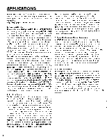
CONTROLS & CONNECTIONS • FRONT PANEL O YAMAHA GRAPHIC EQUALIZER GQ RBI O POWER EOO INPU LEVEL NEAR lo - i0 20 25 ...ON OE , . I 40 50 63 80 100 125 .0 700 250 315 400 500 630 800 1k 1 5x 162k zsx 31sk 5k 6 3k 8k ID 2 5 .k 20kHz - - 111[111 - 3 9tle c) • REAR PANEL C) CO O e ® \O OUT UTT INPUT OO PUT INPUT CAUTION TO PREVENT ELECTRIC .0, 00 NOT REMOVE VW SCREWS NO USENSERVICCANI RA., INSICS RFEELL .I.. MOWS/OSP SERV, PERSONNEL ATTENTION- Ant, . PREEMIE UN CI.. ELECTS/Out NJ PPS ENLEVER LES VIS I, Dr , EpousE A L INEEELERN µwow WARNING: To REDUCE D. VP, , nnE OR SLESTRIC NOCK DO NOT EXPOSS IS APPLIANCE IO RAIN OR SIONTURE =,eZV ,'njr,nnIZZLn .grAWAr ® YAMAHA (t)S GRAPHIC EQUALIZER MO0DEL 00.31 12 60Hz MIAPDPEOIN SAKI(' CO.,LTD. MADE N JAPAN Voltage Selector (General model only) U.S. & Canadian models 0 POWER Switch Press this switch to turn AC power to the equalizer ON. The POWER indicator lamp located above the POWER switch will light to indicate that power is ON. Press a second time to turn power OFF. NOTE: The GQ1031 incorporates a special power-on surge protection system which bypasses the equalizer circuitry for approximately 2 seconds after power is turned ON, even if the EQ switch is ON (see "EQ Switch" below). 0 EQ Switch This switch determines whether the equalizer circuitry is on or bypassed -that is, whether the input signal is routed through the EQ circuitry or directly to the output, "bypassing" the equalizer circuitry. INPUT 0 OUT 0 I IN EQUALIZER CIRCUITRY O OUT -ere, IN • 0 OUTPUT The EQ indicator LED above the EQ switch will light when the EQ circuitry is ON. This switch is useful for comparing the equalized and unequalized signal. 0 INPUT LEVEL Control and PEAK Indicator This control sets the sensitivity of the equalizer's input stage, permitting optimum level matching with a wide range of sources. With the INPUT LEVEL control set at maximum its position ("10" on the scale) the nominal input level of the GQ1031 is -10dB - this produces a -10dB output level - and the maximum input level is +20 dB, producing a +20 dB output. The INPUT LEVEL control can be used to increase or decrease the equalizer's input sensitivity, permitting input of signals that are higher or lower than the rated level. The maximum output level of the GQ1031 is +20dB, however, the PEAK indicator LED lights when the equalizer's output level reaches or exceeds +17 dB, warning of overload distortion. Since equalizing a signal can also affect its overall level, the INPUT LEVEL control can also be used to match the levels of the equalized and bypassed (unequalized sound). With proper equalization technique, however, this should not be necessary. L E0 Switch in " IN " position 3
-
 1
1 -
 2
2 -
 3
3 -
 4
4 -
 5
5 -
 6
6 -
 7
7 -
 8
8
 |
 |
