Yamaha HTR-5450RDS Owner's Manual - Page 16
Connecting Video Components, Audio signal jacks, TV monitor with a 21-pin connector, S VIDEO jacks
 |
View all Yamaha HTR-5450RDS manuals
Add to My Manuals
Save this manual to your list of manuals |
Page 16 highlights
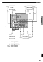
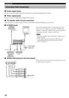
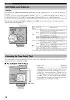
CONNECTIONS Connecting Video Components I Audio signal jacks Be sure to connect the right channel (R), left channel (L), input (IN) and output (OUT) properly. I Video signal jacks Be sure to connect the input (IN) and output (OUT) properly. I TV monitor with a 21-pin connector Make a connection as shown on page 15 with a commercially available SCART-plug connector cable. I S VIDEO jacks DVD player S VIDEO OUT Video monitor S VIDEO IN S S VIDEO SIGNAL DVD D-TV/CBL IN VCR 1OUT MONITOR OUT VIDEO S VIDEO If your video component has "S" (high-resolution) video jacks, they can be connected to this unit's S VIDEO jacks. Otherwise, connect the composite video jacks of your video component to this unit's composite video jacks. Notes • Use a special S VIDEO cable (commercially available) for the S VIDEO connection. • If video signals are input from both the S VIDEO input and composite input jacks, the signals will be directed to their respective output jacks. S S S S VIDEO OUT S VIDEO OUT S S VIDEO IN S Video signal Signal flow TV/digital TV, cable TV or satellite tuner VCR I VIDEO AUX jacks (on the front panel) S VIDEO VIDEO L AUDIO R OPTICAL These jacks are used to connect any video input source such as a game console to this unit. VIDEO AUX S V L R O OPTICAL OUT AUDIO OUT R AUDIO OUT L VIDEO OUT S VIDEO OUT Game console 14
-
 1
1 -
2
-
3
-
4
-
5
-
6
-
7
-
8
-
9
-
10
-
 11
11 -
 12
12 -
 13
13 -
 14
14 -
 15
15 -
 16
16 -
 17
17 -
 18
18 -
 19
19 -
 20
20 -
 21
21 -
22
-
23
-
24
-
25
-
26
-
27
-
28
-
29
-
30
-
31
-
32
-
33
-
34
-
35
-
36
-
37
-
38
-
39
-
40
-
41
-
42
-
43
-
44
-
45
-
46
-
47
-
48
-
49
-
50
-
51
-
52
-
53
-
54
-
55
-
56
-
57
-
58
-
59
-
60
-
61
-
62
-
63
-
64
-
65
-
66
-
67
-
68
-
69
-
70
-
71
 |
 |
