Yamaha HTR-5490 Owner's Manual
Yamaha HTR-5490 Manual
 |
View all Yamaha HTR-5490 manuals
Add to My Manuals
Save this manual to your list of manuals |
Yamaha HTR-5490 manual content summary:
- Yamaha HTR-5490 | Owner's Manual - Page 1
U HTR-5490 AV Receiver OWNER'S MANUAL IMPORTANT Please record the serial number of this unit in the space below. MODEL: Serial No.: The serial number is located on the rear of the unit. Retain this Owner's Manual in a safe place for future reference. - Yamaha HTR-5490 | Owner's Manual - Page 2
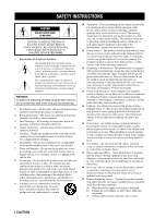
INSTRUCTIONS CAUTION RISK OF ELECTRIC SHOCK DO NOT OPEN CAUTION: TO REDUCE THE RISK OF ELECTRIC SHOCK, DO NOT REMOVE COVER (OR BACK). NO USER-SERVICEABLE PARTS INSIDE. REFER SERVICING TO QUALIFIED SERVICE lines or circuits. When installing an outside antenna system, extreme care should be taken to - Yamaha HTR-5490 | Owner's Manual - Page 3
ANTENNA GROUNDING MAST GROUND CLAMP ELECTRIC SERVICE EQUIPMENT NEC - NATIONAL ELECTRICAL CODE ANTENNA LEAD IN WIRE ANTENNA according to the instructions found in the users manual, may cause can be determined by turning the unit "OFF" and "ON", please try to eliminate the problem by using one of - Yamaha HTR-5490 | Owner's Manual - Page 4
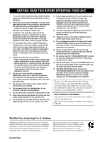
this manual carefully right and left, and at the back of this unit - away from direct may cause electrical shock to the user and/or damage to this unit Contact qualified YAMAHA service personnel when any service is SELECTOR on the rear panel of this unit must this unit itself is turned off. This state - Yamaha HTR-5490 | Owner's Manual - Page 5
3 Installing Batteries in the Remote Control 3 CONTROLS AND FUNCTIONS 4 Front Panel 4 Remote Control 6 Using the Remote Control 7 Front Panel Display 8 Rear Panel 9 PREPARATION SPEAKER SETUP 10 Speakers to Be Used 10 Speaker Placement 10 Connecting the Speakers 11 CONNECTIONS 14 Before - Yamaha HTR-5490 | Owner's Manual - Page 6
name on the remote control is given in parentheses in this manual. Manufactured under license from Dolby Laboratories. "Dolby", "Pro Logic", and the double-D symbol are trademarks of Dolby Laboratories. "DTS", "DTS-ES Extended Surround" and "Neo: 6" are trademarks of Digital Theater System, Inc - Yamaha HTR-5490 | Owner's Manual - Page 7
INDEX Indoor FM antenna (U.S.A., Canada and China models) (Australia model) Connection Guide CONNECTION GUIDE Connection with a DVD player This connection guide shows the basic way to connect this unit to a DVD player to enjoy 5.1 channel digital sources. Carefully connect the speakers with this - Yamaha HTR-5490 | Owner's Manual - Page 8
Front Panel 1 CONTROLS AND FUNCTIONS 2 3 45 67 NATURAL SOUND AV RECEIVER STANDBY /ON D I G I TA L INPUT M0DE INPUT VOLUME 6CH INPUT SPEAKERS A B BASS PROCESSOR EXTENSION DIRECT TUNER DSP A/B/C/D/E PRESET/ TUNING STEREO EFFECT PROGRAM PRESET TUNING /TUNING FM/AM MEMORY MODE - Yamaha HTR-5490 | Owner's Manual - Page 9
that the "AUTO" indicator lights up on the front panel display. To select the manual tuning mode, press this button so that the "AUTO" indicator does not light up. a BASS Adjusts the low-frequency response for the left and right main channels. Turn the control to the right to increase or to the left - Yamaha HTR-5490 | Owner's Manual - Page 10
such as play, stop, skip, etc. for operating your other components. 0 LEVEL Selects the effect speaker channel to be adjusted and sets the level. q Multi control section Functions vary depending on your components that are set up with the manufacturer code. w TEST Outputs the test tone to adjust the - Yamaha HTR-5490 | Owner's Manual - Page 11
DTS audio signals except for the LFE channel are also directed to the main left and right speakers. CONTROLS AND FUNCTIONS Using the Remote Control NATURAL SOUND AV RECEIVER STANDBY /ON D I G I TA L INPUT M0DE INPUT VOLUME 6CH INPUT SPEAKERS A B BASS PROCESSOR EXTENSION DIRECT TUNER DSP - Yamaha HTR-5490 | Owner's Manual - Page 12
, MOVIE THEATER 1, MOVIE THEATER 2 or V/DTS SURROUND DSP program is selected. w Multi-information display Shows the current DSP program name and other information when adjusting or changing settings. e STEREO indicator Lights up when this unit is receiving a strong signal for an FM stereo broadcast - Yamaha HTR-5490 | Owner's Manual - Page 13
OPERAIONT Rear Panel 12 3 *1 4 CONTROLS AND FUNCTIONS VCR 2 /DVR OUT TUNER AM ANT GND 75Ω UNBAL. FM ANT MONITOR OUT S VIDEO VIDEO OUTPUT SUB WOOFER IMPEDANCE SELECTOR SET BEFORE POWER ON model) 9 Antenna input terminals See page 36 for connection information. 0 Speaker terminals See pages - Yamaha HTR-5490 | Owner's Manual - Page 14
) channel with high fidelity when the Dolby Digital signal or the DTS signal is played back. The YAMAHA Active Servo Processing Subwoofer System is ideal for natural and lively bass reproduction. Refer to the following diagram when you place the speakers. Center speaker Main speaker (R) Rear - Yamaha HTR-5490 | Owner's Manual - Page 15
connections is incorrect, the sound will be unnatural and lack bass. CAUTION • Use speakers with the specified impedance shown on the rear panel of this unit. • Do not let the bare speaker wires touch each other and do not let them touch any metal part of this unit. This could damage this unit - Yamaha HTR-5490 | Owner's Manual - Page 16
the subwoofer. It is also possible to adjust the volume level by using the remote control of this unit (see ADJUSTING THE LEVEL OF THE EFFECT SPEAKERS on page 63). • Depending on the settings of "1 SPEAKER SET" and "10 LFE LEVEL" on the SET MENU, some signals may not be output from the SUBWOOFER - Yamaha HTR-5490 | Owner's Manual - Page 17
INTRODUCTION PREPARATION I IMPEDANCE SELECTOR switch SPEAKER SETUP WARNING Do not change the IMPEDANCE SELECTOR switch setting while the power of this unit is on, otherwise this unit may be damaged. If this unit fails to turn on when STANDBY/ON (or SYSTEM POWER) is pressed, the IMPEDANCE - Yamaha HTR-5490 | Owner's Manual - Page 18
Refer to the operation instructions for each component to be connected to this unit. • When you connect other YAMAHA audio components (such jacks, check the details in the owner's manual that came with the component being connected. I VIDEO AUX jacks (on the front panel) S VIDEO VIDEO L AUDIO R - Yamaha HTR-5490 | Owner's Manual - Page 19
VIDEO PR/ CR PB/ CB Y DVD D-TV / LD MONITOR OUT IN VCR 1 OUT IN VCR 2 /DVR OUT TUNER AM ANT GND 75Ω UNBAL. FM ANT MONITOR OUT S VIDEO VIDEO R L (UM.ASIN .A. model) SUB WOOFER R MAIN L + A - - B + S S VIDEO OUTPUT V VIDEO OUTPUT AUDIO OUTPUT Cable TV or Satellite tuner LR - Yamaha HTR-5490 | Owner's Manual - Page 20
from a source component connected to this unit while this unit is set in the standby mode, the recorded sound may be distorted. To avoid this problem, turn on this unit. 16 - Yamaha HTR-5490 | Owner's Manual - Page 21
(REC) DVD CD CBL /SAT IN VCR 1 OUT MONITOR OUT TUNER AM O ANT GND D-TV /LD PHONO CD MAIN IN VCR 2 /DVR OUT 75Ω UNBAL. FM ANT COAXIAL CBL /SAT SURROUND MONITOR OUT DIGITAL INPUT GND SUB CENTER WOOFER 6CH INPUT S VIDEO VIDEO GND OUTPUT LR Turntable indicates signal direction - Yamaha HTR-5490 | Owner's Manual - Page 22
in amplifier, including the YAMAHA Active Servo Processing Subwoofer remote control of this unit (see ADJUSTING THE LEVEL OF THE EFFECT SPEAKERS on page 63). • Depending on the settings of "1 SPEAKER channels. Notes • When you select 6CH INPUT as the input source, this unit automatically turns - Yamaha HTR-5490 | Owner's Manual - Page 23
is controlled by turned SPEAKER REAR CENTER: 6ΩMIN. /SPEAKER REAR : 6ΩMIN. /SPEAKER MAIN A OR B: 8ΩMIN. /SPEAKER A+B: 16ΩMIN. /SPEAKER CENTER : 8ΩMIN. /SPEAKER REAR CENTER: 8ΩMIN. /SPEAKER REAR : 8ΩMIN. /SPEAKER AC OUTLETS I VOLTAGE SELECTOR (China model only) The VOLTAGE SELECTOR on the rear panel - Yamaha HTR-5490 | Owner's Manual - Page 24
MD/TAPE CD-R D-TV/LD VCR 1 VCR2/DVR DVD POWER TV REC SELECT POWER AV AMP 1 Press STANDBY/ON (SYSTEM POWER on the remote control) to turn on the power of this unit. SYSTEM POWER STANDBY /ON or Front panel Remote control The level of the main volume, and then the current DSP program name - Yamaha HTR-5490 | Owner's Manual - Page 25
on the front panel display. y • Turn on the video monitor connected to this unit. 2 Make sure the AMP mode is selected and press ON SCREEN on the remote control TV REC DISC SKIP POWER AV AMP AUDIO + VOL - LEVEL MOVIE 7 MOVIE THEATER 1 8 MOVIE THEATER 2 9 / • Playing back video software - Yamaha HTR-5490 | Owner's Manual - Page 26
SP 1C REAR L/R SP 1D REAR CT SP 1E LFE/BASS OUT 1F MAIN LEVEL Description Control value (default setting indicated in bold) Selects the output mode according to whether or not a center speaker is being used and its performance. LRG/SML/NONE Selects the output mode according to the performance - Yamaha HTR-5490 | Owner's Manual - Page 27
The adjustment of each speaker output level should be made at your listening position with the remote control. After completing the adjustments, use VOL +/- at your listening position to check if the adjustments are satisfactory. 3 Before You Begin NATURAL SOUND AV RECEIVER STANDBY /ON D I G I TA - Yamaha HTR-5490 | Owner's Manual - Page 28
panel display also indicates from which speaker the test tone is output in the order of TEST LEFT¡TEST CENTER¡TEST RIGHT¡ TEST R SUR.¡TEST REAR CNTR¡TEST L SUR. Note • If the test tone cannot be heard, turn , the center channel sound is automatically output from the left and right main speakers. • If - Yamaha HTR-5490 | Owner's Manual - Page 29
THEATER 1 8 MOVIE THEATER 2 9 /DTS SUR. 10 0 SELECT 11 +10 6.1/ES 12 CHP/INDEX 6 7 1 Press STANDBY/ON (SYSTEM POWER on the remote control) to turn on the power. SYSTEM POWER STANDBY /ON or Front panel Remote control 2 Turn on the video monitor connected to this unit. 3 Press SPEAKERS - Yamaha HTR-5490 | Owner's Manual - Page 30
panel BASS TREBLE Remote control BASS PROCESSOR EXTENSION DIRECT - +- + Note • If the component connected to the VCR 1 OUT, VCR 2/DVR OUT, CD-R OUT and MD/TAPE OUT jacks is turned off, the reproduced sound may be distorted or the volume may be lowered for the characteristics of AV receivers - Yamaha HTR-5490 | Owner's Manual - Page 31
turn VCR2/DVR DVD Front panel Remote control V AUX VCR2/ instructions for the player.) Note the following when a 96kHz sampling digital signal is input to this unit: - DSP programs cannot be selected. Sound will be output as normal 2-channel stereo sound from only the left and right main speakers - Yamaha HTR-5490 | Owner's Manual - Page 32
AV RECEIVER STANDBY /ON D I G I TA L INPUT M0DE INPUT PRO LOGIC VOLUME 6CH INPUT SPEAKERS THEATER 1 8 MOVIE THEATER 2 9 /DTS SUR. 10 0 SELECT 11 +10 6.1/ES 12 CHP/INDEX Front panel Remote control are memorized and are automatically selected when you turn on the power again. • If a Dolby - Yamaha HTR-5490 | Owner's Manual - Page 33
pressing PROGRAM l / h on the front panel. PROGRAM Front control or Select PRO LOGIC by pressing the numeric button 10 on the remote control. HALL 1 CHURCH 2 JAZZ CLUB 3 ROCK CONCERT 4 ENTERTAINMENT 5 TV SPORTS 6 MONO MOVIE 7 MOVIE THEATER 1 8 MOVIE THEATER 2 9 /DTS SUR. 10 0 SELECT 11 - Yamaha HTR-5490 | Owner's Manual - Page 34
center speaker does not work for 5.1 channel sources. turn the sound effect back on. STEREO EFFECT STEREO or EFFECT Front panel Remote control Notes • If you turn off the sound effect, no sound is output from the center speaker, rear speakers, rear center speaker and subwoofer. • If you turn - Yamaha HTR-5490 | Owner's Manual - Page 35
room. The traditional stereo system that uses only two speakers is not capable of recreating a realistic sound field. YAMAHA's DSP requires four effect speakers to recreate sound fields based on the measured sound field data. The processor controls the strength and delay time of the signals output - Yamaha HTR-5490 | Owner's Manual - Page 36
right on the screen, the effect sound a little farther back, the music spread even farther back, and the surround sound around the listener. Of course, -DSP sound field programs, YAMAHA's exclusive DSP processing is added to the right and left Main and Center channels, so the listener can enjoy - Yamaha HTR-5490 | Owner's Manual - Page 37
provide the same quality of sound and sound localization that 6-channel soundtracks do. The built-in Dolby Digital or DTS decoder brings the professional-quality sound designed for movie theaters into your home. With this unit's MOVIE THEATER programs, you can recreate a dynamic sound that gives you - Yamaha HTR-5490 | Owner's Manual - Page 38
2 channel 5.1 channel 6.1 channel *1 No. Program Stereo DOLBY DIGITAL DTS DOLBY DIGITAL DTS ES 8 MOVIE THEATER 1 turn on and the corresponding DSP program will be selected. • 6.1/ES on the remote control can be used to play Dolby Digital or DTS 5.1 channel sources with rear center speaker - Yamaha HTR-5490 | Owner's Manual - Page 39
This program ideally simulates the multi-surround speaker systems of the 35-mm film theaters. Dolby Pro Logic decoding, Dolby Digital field wrap around the viewer naturally from the back to the left and right, and toward the screen. I For audio-video sources in 2-channel: No. 5 to 7 No. Program - Yamaha HTR-5490 | Owner's Manual - Page 40
panel) according to the frequency spacing in your area. North, Central and South America: 100 kHz/10 kHz Other area: 50 kHz/9 kHz Before setting this switch, disconnect the AC power plug of this unit from the AC outlet. AM loop antenna (included) (U.S.A. model) Indoor FM antenna (included - Yamaha HTR-5490 | Owner's Manual - Page 41
is no interference. When using the remote control to proceed some of the steps in "TUNING", make sure the "TUNER" mode is selected. 1 NATURAL SOUND AV RECEIVER STANDBY /ON D I G I TA L INPUT M0DE INPUT PRO LOGIC VOLUME 6CH INPUT SPEAKERS A B BASS PROCESSOR EXTENSION DIRECT TUNER DSP - Yamaha HTR-5490 | Owner's Manual - Page 42
NATURAL SOUND AV RECEIVER STANDBY /ON D I G I TA L INPUT M0DE INPUT PRO LOGIC VOLUME 6CH INPUT SPEAKERS A B FM stations and/or begin tuning toward lower frequencies. After pressing MEMORY in step 3: 1. Press A/B/C/D/E and PRESET/TUNING l / h (A/B/ C/D/E and PRESET j / i on the remote control - Yamaha HTR-5490 | Owner's Manual - Page 43
CH + PRESET Remote control 1 Tune in to a station. See page 37 for tuning instructions. V AUX VCR2/DVR VCR 1 CBL/SAT D TV/LD DVD MD/TAPE CD R TUNER CD PHONO MUTE VOLUME SLEEP SP A A M 576 kHz L R A When tuned in to a station, the front panel display shows the frequency of received station - Yamaha HTR-5490 | Owner's Manual - Page 44
TV SPORTS 6 MONO MOVIE 7 MOVIE THEATER 1 8 MOVIE THEATER 2 9 /DTS SUR. 10 0 SELECT 11 +10 6.1/ES 12 CHP/INDEX 1 2 1 Press A/B/C/D/E (A/B/C/D/E on the remote control) to select the preset station group. The preset group letter appears on the front panel display and changes each time you press - Yamaha HTR-5490 | Owner's Manual - Page 45
POWER TV REC SELECT POWER AV AMP 1 Turn on the power of this unit and all connected component. 2 Select the source component you want to record from. INPUT or A PHONO TUNER CD V-AUX CBL/SAT MD/TAPE CD-R D-TV/LD VCR 1 VCR2/DVR DVD Front panel Remote control 3 Start playback (or select - Yamaha HTR-5490 | Owner's Manual - Page 46
REMOTE CONTROL FEATURES The remote control can operate other A/V components of YAMAHA and other manufacturers as well as this unit. To control those components, you must set up remote control with the manufacturer codes. This remote control DISC SKIP POWER AV AMP AUDIO THEATER 1 8 MOVIE THEATER - Yamaha HTR-5490 | Owner's Manual - Page 47
REMOTE CONTROL FEATURES Setting the Manufacturer Code You can control other components by setting a manufacturer code. A code can be set up in each component control being set. If it does, the manufacturer code setting has been correctly made. POWER TV POWER AV AMP REC DISC SKIP AUDIO + VOL - Yamaha HTR-5490 | Owner's Manual - Page 48
or extremely long transmissions. (Refer to the operation instructions for the other remote control.) 1 Press an input selector button or Å into this remote control until "OK" appears in the display window. 6CH INPUT SLEEP STANDBY SYSTEM POWER RE-NAME CLEAR LEARN TRANSMIT POWER AV POWER TV - Yamaha HTR-5490 | Owner's Manual - Page 49
FEATURES Changing the Source Name in the Display Window You can change the name that appears in the display window on the remote control if you want to use the different name from the original input selector button names. This is useful when different component is set in the - Yamaha HTR-5490 | Owner's Manual - Page 50
REMOTE CONTROL FEATURES Clearing Learned Functions, Renamed Source Names, and Setup Manufacturer Codes 4 Press and hold CLEAR to select the area for which you want to clear the name, function or manufacturer code. SYSTEM POWER STANDBY SLEEP 6CH INPUT A PHONO TUNER CD V-AUX CBL/SAT MD/TAPE - Yamaha HTR-5490 | Owner's Manual - Page 51
INTRODUCTION PREPARATION BASIC OPERATION REMOTE CONTROL FEATURES Each Component Control Area The general operational buttons are shown for each area. Some of them may not function depending on the component you have. After setting the manufacturer code, press an input selector button or Å, or - Yamaha HTR-5490 | Owner's Manual - Page 52
REMOTE CONTROL THEATER 2 9 /DTS SUR. 10 0 SELECT 11 +10 6.1/ES 12 CHP/INDEX Power Sound Play Skip forward Search forward Display Chapter/time The buttons in parentheses above (AV POWER, REC, d, w, t/y, a) function to operate your VCR without switching the input to VCR 1 if the manufacturer code - Yamaha HTR-5490 | Owner's Manual - Page 53
REMOTE CONTROL POWER AV THEATER 2 9 /DTS SUR. 10 0 SELECT 11 +10 6.1/ES 12 CHP/INDEX Power Pause Skip forward Play Search forward Stop Display Index * TV POWER, TV INPUT, TV channel +/-, TV volume +/- and TV MUTE function to operate your TV without switching the input if the manufacturer code - Yamaha HTR-5490 | Owner's Manual - Page 54
THEATER 2 9 /DTS SUR. 10 0 SELECT 11 +10 6.1/ES 12 CHP/INDEX Power A/B/C/D/E Preset up * TV POWER, TV INPUT, TV channel +/-, TV volume +/- and TV MUTE function to operate your TV without switching the input if the manufacturer code is set in D-TV/LD or PHONO. When the manufacturer code for - Yamaha HTR-5490 | Owner's Manual - Page 55
remote control without making connection to this unit. The shaded area shown below can be used for the component set in Å and the function for each button differs depending on the component. YAMAHA LD player is factory-set in Å. However if you want to set other component, set the manufacturer code - Yamaha HTR-5490 | Owner's Manual - Page 56
panel display on this unit while adjusting the items. Note • The indication on the front panel display is the abbreviation of the OSD. 1 SPEAKER should be made with the remote control. TRANSMIT RE-NAME CLEAR LEARN TV SPORTS 6 MONO MOVIE 7 MOVIE THEATER 1 8 MOVIE THEATER 2 9 /DTS SUR. 10 - Yamaha HTR-5490 | Owner's Manual - Page 57
MOVIE 7 MOVIE THEATER 1 8 MOVIE THEATER 2 9 /DTS SUR. 10 0 SELECT 11 +10 6.1/ES 12 CHP/INDEX SET MENU 1 SPEAKER SET (speaker mode settings) center speaker. The entire range of the center channel signal is directed to the center speaker. 1A CENTER SP Memory back-up The memory back-up circuit - Yamaha HTR-5490 | Owner's Manual - Page 58
• When you select MAIN for "1E LFE/BASS OUT", the lowfrequency signals (90 Hz and below) of the main channel are directed to the main speakers even if you select SMALL for the main speaker mode. y • This unit is set in the virtual CINEMA DSP mode by selecting NONE for "1C REAR L/R SP - Yamaha HTR-5490 | Owner's Manual - Page 59
, this unit can provide more realistic frontto-back and transitions. The initial setting is "LRG". Choices: LRG (large), SML (small), NONE Initial setting: LRG LRG Select this if you have a large rear center speaker. The entire range of the rear center channel signal is directed to the rear center - Yamaha HTR-5490 | Owner's Manual - Page 60
matches that of the other speakers in your configuration. Change the setting with the remote control while sitting in the speakers with that of your main speakers when using the test tone. 1F MAIN LEVEL Normal -10dB Notes • Do not turn up the volume too high. • If no test tone is heard, turn - Yamaha HTR-5490 | Owner's Manual - Page 61
listening room. Low-frequency sounds are especially affected by the listener's position, speaker placement, subwoofer polarity and other conditions. Digital generator (wide band noise produced) 4 HP TONE CTRL (headphone tone control) Use this feature to adjust the level of the bass and treble when - Yamaha HTR-5490 | Owner's Manual - Page 62
change the name of the input which appears on the OSD or the front panel display. 1 Press an input selector button (or use INPUT l / h) to that component with INPUT l / h (or the input selector buttons on the remote control). I 7A CMPNT-V INPUT for COMPONENT VIDEO INPUT jacks [A] and [B] Choices: - Yamaha HTR-5490 | Owner's Manual - Page 63
SET MENU 8 INPUT MODE (initial input mode) Use this feature to designate the input mode for sources connected to the DIGITAL INPUT jacks when you turn on this unit (see page 27 for details about the input mode). 8 INPUT MODE AUTO LAST -/+ : Select / : Exit Choices: AUTO, LAST Initial setting: AUTO - Yamaha HTR-5490 | Owner's Manual - Page 64
the output level of the LFE (low-frequency effect) channel when playing back a Dolby Digital or DTS signal. The LFE signal carries the low-frequency special effect sound which is only added to certain scenes. Control range (dB): -20 to 0 for both SPEAKER and HEADPHONE Initial setting: 0 dB for both - Yamaha HTR-5490 | Owner's Manual - Page 65
for the Center speaker is especially important for giving depth to the dialogue. Control range: 0 to 5 ms for CENTER 0 to 30 ms for REAR CENTER Initial setting: 0 ms for CENTER 3 ms for REAR CENTER Press j / i to increase or decrease the delay of the center and the rear center channel sounds. 12 SP - Yamaha HTR-5490 | Owner's Manual - Page 66
ON, OFF Initial setting: OFF I BLUE BACK Selecting AUTO for the on-screen display setting features: • DSP program parameters • All SET MENU items • Center, rear speakers, rear center, and subwoofer levels • The on-screen display (OSD) panel display. Control range: -4 to 0 Initial setting: 0 62 - Yamaha HTR-5490 | Owner's Manual - Page 67
BASIC OPERATION ADJUSTING THE LEVEL OF THE EFFECT SPEAKERS You can adjust the output level of each effect speaker (center, left and right rear and subwoofer) while listening to a music source. Adjustment should be made with the remote control. TRANSMIT RE-NAME CLEAR LEARN SYSTEM POWER STANDBY - Yamaha HTR-5490 | Owner's Manual - Page 68
timer also automatically turns off the external components connected to AC OUTLET(S). The sleep timer can only be set with the remote control. y • By connecting a commercially available timer to this unit, you can also set a wake-up timer. Refer to the operation instructions of the timer. Setting - Yamaha HTR-5490 | Owner's Manual - Page 69
surface - walls, ceiling, the back of the room - so numerous sound fields at will is exactly what YAMAHA has done with the digital sound field control these and many other factors that contribute to your personal sound field, allowing you to essentially "redesign" the concert halls, theaters - Yamaha HTR-5490 | Owner's Manual - Page 70
remote control. panel display. 1 TRANSMIT RE-NAME CLEAR LEARN SYSTEM POWER STANDBY SLEEP 6CH INPUT A PHONO TUNER CD V-AUX CBL/SAT MD/TAPE CD-R D-TV/LD VCR 1 VCR2/DVR DVD POWER TV REC SELECT POWER AV MONO MOVIE 7 MOVIE THEATER 1 8 MOVIE THEATER 2 9 /DTS back-up The memory back 2 Turn on - Yamaha HTR-5490 | Owner's Manual - Page 71
is repeatedly reflected around a room, the larger the hall is, the longer the time between the original reflected sound and the subsequent reflections. By controlling the time between the reflected sounds, you can change the apparent size of the virtual venue. Changing this parameter from one to two - Yamaha HTR-5490 | Owner's Manual - Page 72
side of the sound field. You can only adjust this parameter when at least two front channels and two rear channels are used. I S. ROOM SIZE (Surround Room Size) Control Range 0.1 - 2.0 Function: This parameter adjusts the apparent size of the surround sound field. I S. LIVENESS (Surround - Yamaha HTR-5490 | Owner's Manual - Page 73
in a larger acoustic environment. Level Sound Source (dB) Reverberation 60 dB Time REV. REV. TIME DELAY I REV. LEVEL (Reverberation Level) Control Range 0 - 100 % Function: This parameter adjusts the volume of the reverberation sound. Description: The larger the value, the stronger the - Yamaha HTR-5490 | Owner's Manual - Page 74
adjust the volume level for each channel in 6-channel stereo mode. For PRO LOGIC Music I PANORAMA Control Range OFF/ON Function: Extends the front stereo image to include the surround speakers for wraparound effect. I DIMENSION Control Range -3 - STD - +3 Function: Gradually adjusts the - Yamaha HTR-5490 | Owner's Manual - Page 75
is not listed below or if the instruction below does not help, set this unit in the standby mode, disconnect the power cord, and contact the nearest authorized YAMAHA dealer or service center. I General Problem Cause Remedy Refer to page This unit fails to turn on when STANDBY/ ON (or SYSTEM - Yamaha HTR-5490 | Owner's Manual - Page 76
of the speakers in your configuration. 53 - 56 "1D REAR CT SP" on the SET MENU Select LRG or SML. 55 is set to NONE. 6.1/ES is not on. Press the 6.1/ES button on the remote control to turn 30 it on. Incorrect cable connections. Firmly connect the audio plugs. If the problem persists, the - Yamaha HTR-5490 | Owner's Manual - Page 77
PREPARATION TROUBLESHOOTING Problem Cause Remedy The volume level is low while playing a record. The volume level cannot be increased, or the sound is distorted. The record is being played on a turntable with an MC cartridge. The component connected to the REC OUT jacks of this unit is turned - Yamaha HTR-5490 | Owner's Manual - Page 78
reception is noisy. The characteristics of FM stereo broadcasts may cause this problem when the transmitter is too far away or the antenna input is poor. Check the antenna connections. Try using a high-quality directional FM antenna. Use the manual tuning method. 36, 37 There is distortion - Yamaha HTR-5490 | Owner's Manual - Page 79
PREPARATION I Remote control TROUBLESHOOTING Problem The remote control does not work nor function properly. Cause Remedy Wrong distance or angle. The remote control will function within a maximum range of 6 m (20 feet) and no more than 30 degrees off-axis from the front panel. Direct - Yamaha HTR-5490 | Owner's Manual - Page 80
a Dolby Digital or DTS 5.1 channel systems. I CINEMA DSP D I G I TA L Since the Dolby Surround and DTS systems were originally designed for use in movie theaters, their effect is best felt in a theater having many speakers and designed for acoustic effects. Since home conditions, such as room - Yamaha HTR-5490 | Owner's Manual - Page 81
YAMAHA has developed a virtual CINEMA DSP algorithm that allows you to enjoy DSP sound field surround effects even without any rear speakers by using virtual rear speakers. It is even possible to enjoy virtual CINEMA DSP in a minimum two-speaker "pulse code modulation", be played back is rear panel, - Yamaha HTR-5490 | Owner's Manual - Page 82
150 µV or less • Channel Separation (1 kHz/10 kHz) CD (5.1 kΩ terminated) to Main L/R 60 dB/45 dB • Tone Control (Main L/R) BASS Boost/Cut 15 kg (33 lbs) • Accessories Remote Control Batteries AM loop antenna Indoor FM antenna Connection Guide *Specifications are subject to change without - Yamaha HTR-5490 | Owner's Manual - Page 83
ELECTRONIQUE FRANCE S.A. RUE AMBROISE CROIZAT BP70 CROISSY-BEAUBOURG 77312 MARNE-LA-VALLEE CEDEX02, FRANCE YAMAHA ELECTRONICS (UK) LTD. YAMAHA HOUSE, 200 RICKMANSWORTH ROAD WATFORD, HERTS WD1 7JS, ENGLAND YAMAHA SCANDINAVIA A.B. J A WETTERGRENS GATA 1, BOX 30053, 400 43 VÄSTRA FRÖLUNDA, SWEDEN
-
 1
1 -
 2
2 -
 3
3 -
 4
4 -
 5
5 -
 6
6 -
 7
7 -
8
-
9
-
10
-
11
-
12
-
13
-
14
-
15
-
16
-
17
-
18
-
19
-
20
-
21
-
22
-
23
-
24
-
25
-
26
-
27
-
28
-
29
-
30
-
31
-
32
-
33
-
34
-
35
-
36
-
37
-
38
-
39
-
40
-
41
-
42
-
43
-
44
-
45
-
46
-
47
-
48
-
49
-
50
-
51
-
52
-
53
-
54
-
55
-
56
-
57
-
58
-
59
-
60
-
61
-
62
-
63
-
64
-
65
-
66
-
67
-
68
-
69
-
70
-
71
-
72
-
73
-
74
-
75
-
76
-
77
-
78
-
79
-
80
-
81
-
82
-
83
 |
 |

OWNER’S MANUAL
HTR-5490
U
AV Receiver
IMPORTANT
Please record the serial number of this unit in the
space below.
MODEL:
Serial No.:
The serial number is located on the rear of the unit.
Retain this Owner’s Manual in a safe place for future
reference.