Yamaha MA2030a MA2030a/PA2030a Owners Manual - Page 2
Troubleshooting, Specifications MA2030a/PA2030a, Controls and Connectors, PRECAUTIONS - manual
 |
View all Yamaha MA2030a manuals
Add to My Manuals
Save this manual to your list of manuals |
Page 2 highlights
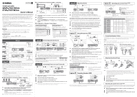
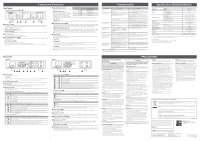
Controls and Connectors Front panel MA2030a (PA2030a has only 4 and 6) 1 23 4 5 6 1 [MIC IN 1] jack Combo input jack that accepts both phone-type and XLR-type. Connect dynamic microphones mainly. Input signal is always processed through high pass filter (120Hz, 12dB/oct.) to cut off low frequency signal and Feedback Suppressor to suppress howling. [MIC IN 1 SIGNAL] indicator Lights when signal is input to the [MIC IN 1] jack. [MIC IN 1] knob Adjusts the volume of the microphone connected to the [MIC IN 1] jack. Turning to the right increases the volume. 2 [ST IN 1] jack Input jack of mini-stereo type (unbalanced input). Connect a stereo audio source such as portable audio players. 3 [ST SOURCE] indicator 1/2/3 Selecting input signal from the [ST IN 1] jack lights indicator 1, the [ST IN 2] jacks lights indicator 2, and the [ST IN 3] jacks lights indicator 3. [ST SOURCE] knob Rotating this switches among the stereo input signals. Pressing and holding this lets you adjust the volume balance of stereo inputs. Refer to "Matching the volume levels of external devices (including microphones)" in "Step 4 Adjusting Volume" for instructions. 4 [VOLUME SIGNAL] indicator Lights when signal output to speakers exceeds a Setting Signal level for which each indicator turns on [VOLUME SIGNAL] certain level. [VOLUME LIMIT] indicator Lights if signal output to the speakers exceeds the limit value, causing the limiter to activate, or if the internal temperature of the device increases abnormally. If the limiter activates, turn the Low-impedance connections High-impedance connections [3Ω] [4Ω] [8Ω] [70V] [100V] -18.2 dBu or more -17.0 dBu or more -14.0 dBu or more -0.8 dBu or more 2.2 dBu or more [VOLUME] knob to the left so the indicator light goes out. If the device internal temperature increases, leave the device without turning on the power until the internal temperature goes down. [VOLUME] knob Adjusts the volume output to the speakers. Turning to the right increases the volume. Turning all the way to the left mutes the sound. 5 [SOURCE EQ BASS] knob Adjust the volume of the low frequency (around 125Hz) stereo signal from -10dB to +10dB. At the center position, the sound is flat; turning to the left lowers the low frequency signal and turning to the right increases the low frequency signal. Turning to the right 90 degrees or more from the center activates the Enhancer to further emphasize the low frequency signal. [SOURCE EQ TREBLE] knob Adjust the volume of the high frequency (6 kHz or more) stereo signal from -10dB to +10dB. At the center position, the sound is flat; turning to the left lowers the high frequency signal and turning to the right increases the high frequency signal. Turning to the right 90 degrees or more from the center activates the Enhancer to further emphasize the high frequency signal. Note If the sound distorts when using EQ, turn the knob to the left until the sound is not distorted or lower the volume of the stereo source. 6 Power indicator Turns on when the power is on. If flashing continues for 10 seconds or more, the internal temperature of the device is extremely high. Turn off the power once, and turn on again several minutes later. Power switch Turn on/off the power. WARNING • To ensure that high-volume noise is not output from the speakers, power on the connected device first and then turn on this device. When turning the system off, turn off this device, and then the connected devices. • After turning the power switch off, wait for about five seconds before turning it on again. Rapidly turning the power switch on and off in succession can cause the unit to malfunction. CAUTION • Even when the switch is in the off position, a small amount of electricity is still flowing to the unit. If it will not be used for an extended period of time, therefore, be sure to unplug the power cord from the wall AC outlet. Note Do not turn off the power switch three seconds or less after executing an operation. If you do, some setting information may not be saved. Troubleshooting Symptom Cause Solution The power does not turn on. The power cord is disconnected. The protection function of the device has been activated. Connect the power cord. Turn off the power switch and make sure the connection is secure. Wait several minutes, and then turn on the power again. No sound is heard. The sound is lowered too much with the [VOLUME] knob. Turn the [VOLUME] knob to the right. No audio signal is being input. Make sure that this device is properly connected to external devices. Make sure that the external device outputs audio signal. The input is not selected. Turn the [ST SOURCE] to select input jacks connected to an external device. The connected microphone is a condenser type. Use a dynamic type microphone or supply phantom power to the condenser microphone. The sound distorts. The input level from microphones or external devices is too high. Turn the [MIC IN 1] knob/the [MIC IN 2 GAIN] trimmer to the left to lower the volume of the microphones. Lower the input volume from the external devices. The EQ level is too high. Turn the [SOURCE EQ BASS]/[SOURCE EQ TREBLE] knob to the left to lower the EQ. The setting does not change even when turning a knob. The panel is locked. When the panel is locked, even when turning the [ST SOURCE] knob, [SOURCE EQ BASS] knob or [SOURCE EQ TREBLE] knob, the setting of the device does not change. Set the panel lock to off. (Press the [ST SOURCE] knob three times within a second.) The sound is weak. The device is set to low-impedance connection; Match the impedance settings of this device and the however, speakers with high-impedance input connected speakers. have been connected. The sound drops out and the power indicator flashes three times. The device is set to high-impedance connection; however, speakers with low-impedance input have been connected or too many speakers are connected. Match the impedance setting and the input rating setting of this device and the speakers. When the device is set to low-impedance connection, the total impedance of the connected speakers is less than the impedance setting of this device. Match the impedance settings of this device and the speakers. The speaker cable is shorted. Inspect the connection of the speaker cables. The power indicator continues flashing. The sound goes off. The internal temperature of the device is extremely high because heat dissipation slits are covered or the device is placed in a confined place with poor ventilation. Turn off the power, leave the device at a well-ventilated place, and turn on the device several minutes later. The device settings do not match speaker impedance. Match the impedance settings of this device and the connected speakers. • Refer also to the Yamaha Pro Audio website that provides a FAQ (a list of frequently asked questions, with answers). http://www.yamahaproaudio.com/ • If taking the above steps does not solve the problem, contact your Yamaha dealer for repair. Specifications (MA2030a/PA2030a) Output Power (20 msec burst, THD+N=1%) Amplifier Type THD+N Frequency Response Crosstalk (MA2030a only) AC Power Requirement Power Consumption (3Ω, AC 100 V) Operating Temperature Storage Temperature Dimensions 8Ω/4Ω/3Ω 70 V/100 V (Output circuitry) Stereo in à Speaker out, 1 kHz, 15 W, 8Ω/4Ω/3Ω Stereo in à Speaker out, 1 kHz, 30 W, 70 V/100 V Line in à Line out, 20 Hz-20 kHz Line in à Speaker out, 50 Hz-20 kHz, 1 W, 8Ω/4Ω/3Ω Line in à Speaker out, 90 Hz-20 kHz, 1 W, 70 V/100 V Stereo in to other Stereo in 1/8 max. power, pink noise at all channel, Idle (W x H x D, including knob) Net Weight Optional Accessories 30 W x 2 ch 60 W x 1 ch Class D ≤ 0.1% ≤ 0.2% 0 dB, -2.5 dB, +1.0 dB 0 dB, -3.0 dB, +1.0 dB 0 dB, -3.0 dB, +1.0 dB ≤ -70 dB 100 V/120 V/230 V-240 V, 50 Hz/60 Hz 30 W 25 W 0°C-+40°C -20°C-+60°C 215 x 54 x 288 mm (8.5 x 2.1 x 11.4 inch) 1.8 kg (4.0 lbs) Rack-mount Accessory RKH1 Digital Control Panel DCP1V4S-US/EU * The contents of this manual apply to the latest specifications as of the publishing date. To obtain the latest manual, access the Yamaha website then download the manual file. European Models Purchaser/User Information specified in EN55103-2:2009. Conforms to Environments: E1, E2, E3 and E4 Rear panel MA2030a 7 89 0 AB C D 7 AC IN connector Connect the supplied power cord. CAUTION • When connecting the power cord, connect the power cord to the connector and then plug it into an appropriate AC power outlet. • Before connecting or disconnecting the power cord, make sure that the power to the device is turned off. 8 [SPEAKERS] output terminals Barrier strip type speaker output connectors. Refer to "Connecting Speaker Cables" for the installation instructions. 9 [OUTPUT] switch Sets the output type of amplifier: high-impedance connection ([100V], [70V]) or low-impedance connection ([8Ω/4Ω/3Ω]). The setting change will be reflected after turning on again. 0 [SETUP] DIP switches Set the following functions of the device. The setting change will be applied after carrying out a power cycle by the Power switch on the front panel. DIP switches 1/2: Speaker impedance setting Sets the speaker impedance if the [OUTPUT] switch is set to [8Ω/4Ω/3Ω] (low-impedance connection). 1 2 Setting 8Ω or more 4Ω to less than 8Ω 3Ω to less than 4Ω DIP switches 3/4: Ducker Configure the settings for the Ducker function. This can mute the microphone input of other channels, and lower the volume of line input when signals are input to [MIC IN 1] or [MIC IN 2]. 3 4 Setting Ducker off Ducker on when signals are input to [MIC IN 2]. Ducker on when signals are input to [MIC IN 1]. Ducker on when signals are input to [MIC IN 1] or [MIC IN 2]. If signals are input to both of them, [MIC IN 1] is given precedence. DIP switches 5/6: Speaker EQ Sets the speaker EQ that corrects the output signal to match the type of speakers that are connected. 5 6 Setting Off High pass filter 150Hz Frequency correction tailored for Yamaha VXS series (Surface mount-type) speakers Frequency correction tailored for Yamaha VXC series (Ceiling-type) speakers PA2030a 7 89 0 E DIP switches 5/6/7: Speaker EQ 5 6 7 Off Setting High pass filter 150Hz Low pass filter 150Hz Low pass filter 200Hz Frequency correction tailored for Yamaha VXS series (Surface mount-type) speakers Frequency correction tailored for the Yamaha VXS10S/VXS10ST subwoofer (45-150Hz) Frequency correction tailored for Yamaha VXC series (Ceiling-type) speakers DIP switch 7: Leveler Use the Leveler function to automatically adjust the volume to a relatively constant range if the input signals vary significantly in volume. 7 Setting Off On DIP switch 8: Mixer In low-impedance installation of speakers, this sets the speaker output to stereo or mono. 8 Setting MONO STEREO Note • When the device is shipped from the factory, the DIP switches are all in the up position. • The output of the [LINE OUT] jacks does not reflect the stereo/mono setting in [SETUP] DIP switch 8 (MIXER). A [DCP] connector Connect one Yamaha Digital Control Panel DCP1V4S-US/EU. Refer to "Option 3 Operating with Control Panel" for connection method. B [LINE OUT] jacks RCA type stereo output jack (unbalanced output). Outputs to the [LINE IN] jacks of PA2030a and line input jacks of other external devices. Outputs a mixed signal of the selected stereo input, the [MIC IN 1] jack input and the [MIC IN 2] jack input. C [ST IN 2] jacks/[ST IN 3] jacks RCA type stereo input jack (unbalanced output). Connect external devices such as CD player, etc. Select input jacks with the [ST SOURCE] knob on the front panel. D [MIC IN 2] connector Euroblock 3-pin connector for microphone audio input (balanced). Refer to "Attaching Euroblock Plugs" for Euroblock plug installation. The input signal is always processed through a high pass filter (120Hz, 12dB/oct.) to cut off low frequency signals as well as a Feedback Suppressor to suppress howling. [MIC IN 2 GAIN] trimmer Adjust the volume of microphone that is connected to the [MIC IN 2] connector. Adjust with a slotted driver of the correct size. E [LINE IN] jacks/connectors RCA type and Euroblock 3-pin stereo input jacks/connectors (RCA: unbalanced; Euroblock 3-pin: balanced). Connect to the [LINE OUT] jacks of the MA2030a or output jacks of other external devices. The signals input from the RCA type jacks and Euroblock connector will be mixed to the output. PRECAUTIONS PLEASE READ CAREFULLY BEFORE PROCEEDING Please keep this manual in a safe place for future reference. WARNING Always follow the basic precautions listed below to avoid the possibility of serious injury or even death from electrical shock, short-circuiting, damages, fire or other hazards. These precautions include, but are not limited to, the following: Power supply/power cord • Do not place the power cord near heat sources such as heaters or radiators, and do not excessively bend or otherwise damage the cord, place heavy objects on it, or place it in a position where anyone could walk on, trip over, or roll anything over it. • Only use the voltage specified as correct for the device. The required voltage is printed on the name plate of the device. • Use only the supplied power cord. If you intend to use the device in an area other than in the one you purchased, the included power cord may not be compatible. Please check with your Yamaha dealer. • Check the electric plug periodically and remove any dirt or dust which may have accumulated on it. • When setting up the device, make sure that the AC outlet you are using is easily accessible. If some trouble or malfunction occurs, immediately turn off the power switch and disconnect the plug from the outlet. Even when the power switch is turned off, as long as the power cord is not unplugged from the wall AC outlet, the device will not be disconnected from the power source. • Remove the electric plug from the outlet when the device is not to be used for extended periods of time, or during electrical storms. • Be sure to connect to an appropriate outlet with a protective grounding connection. Do not open • This device contains no user-serviceable parts. Do not open the device or attempt to disassemble the internal parts or modify them in any way. If it should appear to be malfunctioning, discontinue use immediately and have it inspected by qualified Yamaha service personnel. Water warning • Do not expose the device to rain, use it near water or in damp or wet conditions, or place on it any containers (such as vases, bottles or glasses) containing liquids which might spill into any openings. If any liquid such as water seeps into the device, turn off the power immediately and unplug the power cord from the AC outlet. Then have the device inspected by qualified Yamaha service personnel. • Never insert or remove an electric plug with wet hands. Hearing loss • Avoid setting volume controls to their maximum. Depending on the condition of the connected devices, doing so may result in feedback that can cause hearing loss and damage the speakers. • Do not use speakers for a long period of time at a high or uncomfortable volume level, since this can cause permanent hearing loss. If you experience any hearing loss or ringing in the ears, consult a physician. • When turning on the AC power in your audio system, always turn on the device LAST, to avoid hearing loss and speaker damage. When turning the power off, the device should be turned off FIRST for the same reason. Fire warning • Do not place any burning items or open flames near the device, since they may cause a fire. If you notice any abnormality • If any of the following problems occur, immediately turn off the power switch and disconnect the electric plug from the outlet. - The power cord or plug becomes frayed or damaged. - Unusual smells or smoke are emitted. - Some object has been dropped into the device. - There is a sudden loss of sound during use of the device. - Cracks or other visible damage appear on the device. Then have the device inspected or repaired by qualified Yamaha service personnel. • If this device should be dropped or damaged, immediately turn off the power switch, disconnect the electric plug from the outlet, and have the device inspected by qualified Yamaha service personnel. CAUTION Always follow the basic precautions listed below to avoid the possibility of physical injury to you or others, or damage to the device or other property. These precautions include, but are not limited to, the following: Power supply/power cord • When removing the electric plug from the device or an outlet, always hold the plug itself and not the cord. Pulling by the cord can damage it. Location • Do not place the device in an unstable position where it might accidentally fall over. • Do not block the vents. This device has ventilation holes at the top/ sides/bottom to prevent the internal temperature from becoming too high. In particular, do not place the device on its side or upside down. Inadequate ventilation can result in overheating, possibly causing damage to the device(s), or even fire. • When installing the device and you wish to dissipate heat on it: --Do not cover it with any cloth. --Do not install it on a carpet or rug. --Make sure the top surface faces up; do not install on its sides or upside down. --Do not use the device in a confined, poorly-ventilated location. Inadequate ventilation can result in overheating, possibly causing damage to the device(s), or even fire. If this device is to be used in a small space other than EIAstandard rack, make sure that there is adequate space around the device: at least 10 cm above, 1 cm below the bottom surface, 10 cm at the sides and 10 cm behind. • Do not place the device in a location where it may come into contact with corrosive gases or salt air. Doing so may result in malfunction. • Before moving the device, remove all connected cables. • If the device is mounted in an EIA standard rack, carefully read the section "Precautions for rack mounting". Inadequate ventilation can result in overheating, possibly causing damage to the device(s), malfunction, or even fire. Connections • Before connecting the device to other devices, turn off the power for all devices. Also, before turning the power of all devices on or off, make sure that all volume levels are set to the minimum. Failing to do so may result in electric shock, or equipment damage. • Use only speaker cables for connecting speakers to the speaker jacks. Use of other types of cables may result in fire. Maintenance • Remove the power plug from the AC outlet when cleaning the device. Handling caution • When the surface of the device heats up, do not touch it until the panel temperature goes down. Touching the surface with its high temperature may cause burns. • Avoid inserting or dropping foreign objects (paper, plastic, metal, etc.) into any gaps or openings on the device (vents, etc.) If this happens, turn off the power immediately and unplug the power cord from the AC outlet. Then have the device inspected by qualified Yamaha service personnel. • Do not rest your weight on the device or place heavy objects on it. Avoid applying excessive force to the buttons, switches or connectors. • Avoid pulling the connected cables to prevent injuries or damage to the device. Yamaha cannot be held responsible for damage caused by improper use or modifications to the device. NOTICE To avoid the possibility of malfunction/ damage to the product, or damage to other property, follow the notices below. Handling and maintenance • Do not use the device in the vicinity of a TV, radio, stereo equipment, mobile phone, or other electric devices. Otherwise, the device, TV, or radio may generate noise. • Do not expose the device to excessive dust or vibration, or extreme cold or heat (such as in direct sunlight, near a heater, or in a car during the day), in order to prevent the possibility of panel disfiguration, unstable operation, or damage to the internal components. • Do not place vinyl, plastic or rubber objects on/under the device, since this might discolor the panel of the device or the objects placed on/under the device. • Keep input cables of microphone, etc., devices that contain sensitive circuits, and the power cord at a distance from speaker cables and fasten the speaker cables in place. Since a large amount of current can flow in a speaker cable, a magnetic field will be generated and may produce radio interference and acoustic noise. • When cleaning the device, use a dry and soft cloth. Do not use paint thinners, solvents, cleaning fluids, or chemicalimpregnated wiping cloths. • Condensation can occur in the device due to rapid, drastic changes in ambient temperature-when the device is moved from one location to another, or air conditioning is turned on or off, for example. Using the device while condensation is present can cause damage. If there is reason to believe that condensation might have occurred, leave the device for several hours without turning on the power until the condensation has completely dried out. • Do not use this device for any purpose other than driving loudspeakers. • If you put the device on a table or a rack, do not remove the rubber feet from the device. • Always turn the power off when the device is not in use. Connectors XLR-type connectors are wired as follows (IEC60268 standard): pin 1: ground, pin 2: hot (+), and pin 3: cold (-). Precautions for rack mounting This unit is rated for operation at ambient temperatures ranging from 0 to 40 degrees Celsius. If the device is mounted with other devices in an EIA standard equipment rack, internal temperatures can exceed the specified upper limit, resulting in impaired performance or failure. If the device is mounted in a rack, always observe the following requirements to avoid heat buildup: • If the device is mounted in a rack with other devices that generate a significant amount of heat, such as a power amplifier, leave more than 1U of space between the device and other devices (both above and below). Also, make sure to either leave any open spaces uncovered or install appropriate ventilating panels to minimize the possibility of heat buildup. • To ensure sufficient airflow, leave the rear of the rack open and position it at least 10 centimeters from walls or other surfaces. If you've installed a fan kit, there may be cases in which closing the rear of the rack will produce a greater cooling effect. Refer to the rack and fan unit manual for details. Information for users on collection and disposal of old equipment: This symbol on the products, packaging, and/or accompanying documents means that used electrical and electronic products should not be mixed with general household waste. For proper treatment, recovery and recycling of old products, please take them to applicable collection points, in accordance with your national legislation. By disposing of these products correctly, you will help to save valuable resources and prevent any potential negative effects on human health and the environment which could otherwise arise from inappropriate waste handling. For more information about collection and recycling of old products, please contact your local municipality, your waste disposal service or the point of sale where you purchased the items. For business users in the European Union: If you wish to discard electrical and electronic equipment, please contact your dealer or supplier for further information. Information on Disposal in other Countries outside the European Union: This symbol is only valid in the European Union. If you wish to discard these items, please contact your local authorities or dealer and ask for the correct method of disposal. (weee_eu_en_02) The model number, serial number, power requirements, etc., may be found on or near the name plate, which is at the bottom of the unit. You should note this serial number in the space provided below and retain this manual as a permanent record of your purchase to aid identification in the event of theft. Model No. Yamaha Eco-Label Yamaha Eco-Label is a mark that certifies products of high environmental performance. Serial No. Yamaha Pro Audio global website http://www.yamahaproaudio.com/ (bottom_en_01) Yamaha Downloads http://download.yamaha.com/ Manual Development Group © 2016 Yamaha Corporation Published 10/2016 KSHD-A0 Printed in China
-
 1
1 -
 2
2
 |
 |
