Yamaha MGP32X Owner's Manual
Yamaha MGP32X Manual
 |
View all Yamaha MGP32X manuals
Add to My Manuals
Save this manual to your list of manuals |
Yamaha MGP32X manual content summary:
- Yamaha MGP32X | Owner's Manual - Page 1
Owner's Manual PRECAUTIONS pages 4 to 5 Setup pages 7 to 9 Troubleshooting pages 40 to 41 EN - Yamaha MGP32X | Owner's Manual - Page 2
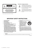
user to the presence of important operating and maintenance (servicing) instructions in the literature accompanying the product. IMPORTANT SAFETY INSTRUCTIONS 1 Read these instructions. 2 Keep these instructions EXPOSE THIS APPARATUS TO RAIN OR MOISTURE. (UL60065_03) 2 MGP32X/MGP24X Owner's Manual - Yamaha MGP32X | Owner's Manual - Page 3
the unit to the factory default settings (resetting user memory)......... 39 Troubleshooting 40 Appendix 42 Message List 42 Effect Program List 43 Parameter List 44 Jack List 46 Dimensions 47 Specifications 48 Index 51 Block Diagram and Level Diagram 52 MGP32X/MGP24X Owner's Manual 3 - Yamaha MGP32X | Owner's Manual - Page 4
contains no user-serviceable parts. Do problems occur, immediately turn off the power switch and disconnect the electric plug from the outlet. Then have the device inspected by Yamaha service easily accessible. If some trouble or malfunction occurs, MGP32X/MGP24X Owner's Manual PA_en_1 1/2 - Yamaha MGP32X | Owner's Manual - Page 5
Yamaha service personnel cause problems with recorder to tip: manual are for instructional purposes only, and may appear somewhat different from those on your device. • Throughout this manual, all panel illustrations show the panel of the MGP32X. • The company names and product names in this manual - Yamaha MGP32X | Owner's Manual - Page 6
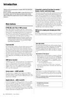
Yamaha MGP32X/MGP24X mixing console. Please read this manual thoroughly to make the best use of the mixing console for the longest possible period of time. After reading this manual, please keep it available for future reference. Main features D-PRE (Discrete Class-A MIC preamp) Mono input channels - Yamaha MGP32X | Owner's Manual - Page 7
using the mixer or ) MGP mixer power time you use the mixer. Failure to do ST switch Channel 4 ON switch channel turn on the channel PFL switch. Adjust from all channels for which the (Stereo) switches for each channel you are using. 3. Make Adjust the volume of each channel by moving its fader - Yamaha MGP32X | Owner's Manual - Page 8
(Yamaha LA-1L) Powered monitor speakers Computer/Audio interface DVD player (voice) DJ mixer CD player Foyer etc. Stage Power amp Powered subwoofer Powered monitor speakers (For musician monitoring) Microphone CH24 {CH16} (for MC) Speakers Powered speakers Synthesizer 8 MGP32X/MGP24X - Yamaha MGP32X | Owner's Manual - Page 9
mixer's inputs, use a DI box (direct box) or amp simulator between the instrument and the mixer. Microphone x 8 Rear panel *The illustrations show the panel of the MGP32X. CAUTION • When using a condenser microphone, set the +48V phantom switch to ON (page 11). Drum MGP32X/MGP24X Owner's Manual - Yamaha MGP32X | Owner's Manual - Page 10
Channel Control Block (input) Mono input section (page 11) Stereo input section (page 11) Master Control Block (output) USB device recorder section (page 17) Channel I/O connectors section (page 22) Master I/O connectors section (page 22) Power section (page 23) 10 MGP32X/MGP24X Owner's Manual - Yamaha MGP32X | Owner's Manual - Page 11
control block Mono input section Stereo input section Mono channels 1-24 (MGP32X) 1-16 (MGP24X) Stereo channels 25-32 (MGP32X) 17-24 (MGP24X) * y-!0 are for CH29/ 30, CH31/32 {CH21/ 22,CH23/24} only. Channel number q 26dB (PAD) switch Turning this switch on ( ) attenuates the input signal - Yamaha MGP32X | Owner's Manual - Page 12
Controls and Connectors Mono channels 1-24 (MGP32X) 1-16 (MGP24X) Stereo channels 25-32 (MGP32X) 17-24 (MGP24X) * y-!0 are for CH29/ 30, CH31/32 {CH21/ 22,CH23/24} only. Channel number Channel number 12 MGP32X/MGP24X Owner's Manual y DUCKER SOURCE indicator The indicator of the selected input - Yamaha MGP32X | Owner's Manual - Page 13
the corresponding buses. If off ( ), the mixer feeds the post-fader signal. !4 FX (effect) knobs (1, 2) These knobs adjust the channel's post-fader signal levels into FX buses 1 and 2. On stereo channels, the LINE L (odd) and LINE R (even) input signals are mixed before moving into the FX bus. These - Yamaha MGP32X | Owner's Manual - Page 14
Controls and Connectors Mono Channel Stereo Channel 1-2 3-4 ST AUX1 AUX2 AUX3 AUX4 14 MGP32X/MGP24X Owner's Manual - Yamaha MGP32X | Owner's Manual - Page 15
Yamaha cannot guarantee operation for all the USB devices). The supported file system is FAT32. The maximum size of one file is 2GB. NOTICE • While the unit is accessing data (such as during recording seconds to pass between turning the mixer on and off and plugging or MGP32X/MGP24X Owner's Manual 15 - Yamaha MGP32X | Owner's Manual - Page 16
COMP button Calls up the display to set the compressor. u USB button Calls up the display to record and play back with the USB device. i SETUP button Calls up the display to adjust the contrast priority over the AFL signal when an input channel's PFL switch is on. 16 MGP32X/MGP24X Owner's Manual - Yamaha MGP32X | Owner's Manual - Page 17
switch's lamp comes on. t SIG (Signal) indicator Lights when an effect signal is input into the channel. y Bus assign switches These switches determine the bus(es) to which the signal of the internal digital to the GROUP1 to GROUP4 buses, and STEREO L/R buses. MGP32X/MGP24X Owner's Manual 17 - Yamaha MGP32X | Owner's Manual - Page 18
on, the indicator will light and the signal after the MATRIX master knob is output to the PHONES and MONITOR OUT jacks for monitoring. 18 MGP32X/MGP24X Owner's Manual - Yamaha MGP32X | Owner's Manual - Page 19
STEREO L/R bus. • TO MONITOR ( ): Sends to the MONITOR OUT jacks and PHONES jack. NOTE CH29/30, 31/32 {CH21/22,23/24} can be selected as the destinations of the signal input from the connected USB device or iPod/ bus, turn on the AFL switch of each respective bus. MGP32X/MGP24X Owner's Manual 19 - Yamaha MGP32X | Owner's Manual - Page 20
Controls and Connectors TALKBACK section GROUP section Use the talkback function to send instructions mainly from the operator to musicians and studio staff. This section adjusts the is enabled, the AFL indicator does not light, even if the AFL switch is pressed. 20 MGP32X/MGP24X Owner's Manual - Yamaha MGP32X | Owner's Manual - Page 21
Controls and Connectors MONO master section This section adjusts the level of the mixed monaural output from the STEREO bus. STEREO master section This section adjusts the level of Adjusts the level of the signal output from the STEREO bus to the STEREO OUT jack. MGP32X/MGP24X Owner's Manual 21 - Yamaha MGP32X | Owner's Manual - Page 22
any given channel, you may use either an XLR or phone jack, but not both. • INSERT: These are unbalanced TRS (tip=send/ Yamaha insertion cable (YIC025/050/070). To the input jack of the external processor To the INSERT jack Sleeve (ground) Ring: IN Tip: OUT Tip: OUT Tip MGP32X/MGP24X Owner's Manual - Yamaha MGP32X | Owner's Manual - Page 23
user. Use M5 screws that are no longer than 20mm. y STEREO INSERT (L, R) These are unbalanced TRS (tip Yamaha recorder, external mixer, or similar device. !0 STEREO OUT (L, R) These are balanced XLR and TRS output jacks that output the mixed cord to the MGP unit, and then MGP32X/MGP24X Owner's Manual 23 - Yamaha MGP32X | Owner's Manual - Page 24
status (>), the playback/recording time, and the title when a problem has occurred. the FX1 RTN (or FX2 RTN) channel when on (highlighted) or off ( when a problem is detected when user memory is problem is detected in the MGP32X/MGP24X internal connection. Press Knob 2 to close the screen. In the case - Yamaha MGP32X | Owner's Manual - Page 25
can adjust the Backlight over a range of 0 to 3. Exiting the screen To return to the HOME screen from the current screen, press the HOME button. MGP32X/MGP24X Owner's Manual 25 - Yamaha MGP32X | Owner's Manual - Page 26
Using Effects (FX) The MGP32X/MGP24X features two built-in effects; FX1 and FX2. FX1 has REV-X reverb (8 types), while FX2 has SPX multi effects (a total of 16 types, including reverb, delay, echo). The effects give you a wide range of tools to further enhance your mixes. Applying effects 1. Press - Yamaha MGP32X | Owner's Manual - Page 27
mode display (indicated by "PARAM" at the bottom). 6. Turn on the ON switch of the FX1 RTN channel, and then raise the FX1 RTN fader to adjust the effect depth. Parameter mode 2. Rotate Knob 1 (for in the display section to switch to the corresponding screen. MGP32X/MGP24X Owner's Manual 27 - Yamaha MGP32X | Owner's Manual - Page 28
of +4.5dB. After you make the settings, it is convenient to save these settings to one of the user programs (page 30). Resetting the selected frequency gain Press and hold Knob 1 for at least two seconds "OK," or Knob 1 to can- cel. All frequency gains will be reset. 28 MGP32X/MGP24X Owner's Manual - Yamaha MGP32X | Owner's Manual - Page 29
set to "ON." Disabling the link allows you to set parameters separately for the right and left channels. 1. Press the GEQ button below the display repeatedly if necessary until the GEQ MODE page appears. 6. Repeat steps 2 -5 as necessary to adjust the GEQ settings. MGP32X/MGP24X Owner's Manual 29 - Yamaha MGP32X | Owner's Manual - Page 30
2 for at least two sec- onds while the user program is selected. The screen prompts you to save the program. 2. Press Knob 2 to select "OK," or Knob 1 to can- cel. The program will be overwritten. NOTE You can also cancel the operation by pressing the GEQ button. 30 MGP32X/MGP24X Owner's Manual - Yamaha MGP32X | Owner's Manual - Page 31
overall sound level. There are three preset programs installed, and you can save up to five user programs as desired. Specifying the compressor settings 1. Press the COMP button below the display repeatedly to select "OK," or Knob 1 to can- cel. The type is changed. MGP32X/MGP24X Owner's Manual 31 - Yamaha MGP32X | Owner's Manual - Page 32
program. 5. Press Knob 2 to select "OK," or Knob 1 to can- cel. The current setting will be overwritten as a user program. NOTE • You can also cancel saving by pressing the COMP button. • Use the MGP Editor (page 6) to change the name of the user program as desired. 32 MGP32X/MGP24X Owner's Manual - Yamaha MGP32X | Owner's Manual - Page 33
back the sound source to be recorded, rotate Knob 1 to adjust the recording level while checking the level meter. The recording level can be adjusted between -48dB and +24dB. Each level of the REC OUT L/R will be displayed on the level meter. Continue to next page MGP32X/MGP24X Owner's Manual 33 - Yamaha MGP32X | Owner's Manual - Page 34
both the STEREO/MONITOR level control (USB IN knob) and the level control for channels 29/30 {21/22} at the same time. Raising both may cause unnatural recording/playback time (hours, minutes, seconds) Remaining recording/playback time (hours, minutes, seconds) 34 MGP32X/MGP24X Owner's Manual - Yamaha MGP32X | Owner's Manual - Page 35
support half-size alpha- bet and numbers only. Other characters are converted into "." • "Recording..." appears at the location of the title while recording outputting to the channel 29/30 {21/22} Use the channel fader to adjust Folder NOTE The title list supports half-size alphabet and numbers - Yamaha MGP32X | Owner's Manual - Page 36
control for channels 31/32 {23/24} at the same time. Raising both may cause unnatural flanging in the sound. 36 MGP32X/MGP24X Owner's Manual 2. Rotate required for recording formats such as WAV and MP3:320k, some USB devices may not be able to record songs. In this case, change the recording format - Yamaha MGP32X | Owner's Manual - Page 37
the channel. 32 {CH21/22 or CH23/24}. To connect the USB device or iPod/iPhone, set the input select switch to USB IN ( ) or iPod IN ( ) respectively. 3. Connect a microphone to the input source channel. For the MGP32X channel to which the microphone is connected in step 3, and then raise the channel - Yamaha MGP32X | Owner's Manual - Page 38
. It is affected by the setting of the ON switch and/or the channel fader. Making detailed Ducker settings 1. Press the SETUP button below the display }, and "#2" indicates CH31/32 {CH23/24}. NOTE For details about the parameters, refer to the Appendix (page 45). 38 MGP32X/MGP24X Owner's Manual - Yamaha MGP32X | Owner's Manual - Page 39
user memory) The MGP32X/MGP24X unit has a function to reset user memory by initializing the unit to the factory default settings. The parameter settings and user programs will be reset to the factory default settings. NOTICE When user progress. Using Other Functions MGP32X/MGP24X Owner's Manual 39 - Yamaha MGP32X | Owner's Manual - Page 40
No sound from the CH29/ 30, CH31/32 {CH21/22, CH23/24} jacks Sound is faint, distorted, or noisy. No effect is applied. I want spoken words to be heard more clearly. I want to output a monitor signal for the mixer through speakers. Cannot record to a USB device Is an independent power - Yamaha MGP32X | Owner's Manual - Page 41
level? You might have to lower the COMP knob levels. Is the GAIN knob on the stereo channels adjusted appropriately? The leveler may not be enabled if you increase the gain too much. * If any specific problem should persist, please contact your Yamaha dealer. MGP32X/MGP24X Owner's Manual 41 - Yamaha MGP32X | Owner's Manual - Page 42
Backup Memory Initialized! User memory was initialized by the procedure on page 39. Cannot be Used While Recording! You attempted to trouble is found in a connection inside the MGP32X/MGP24X. Please contact your Yamaha dealer. Message Device Check Error! XXXXXXXX Meaning There is a problem - Yamaha MGP32X | Owner's Manual - Page 43
the same phrase. Reproduces a lo-fi feel in the style of the AM radio. Adjust the parameter to change the frequency range to be emphasized. MGP32X/MGP24X Owner's Manual 43 - Yamaha MGP32X | Owner's Manual - Page 44
(KARAOKE ECHO) 20.0 - 743.0 ms (DELAY) Delay time VOCAL ECHO R channel = the value in the left column plus 33.0 ms KARAOKE ECHO R channel = the value in the left column plus 65.0 ms FB Level -63 to frequency Modulation depth Feedback level Delay offset Description 44 MGP32X/MGP24X Owner's Manual - Yamaha MGP32X | Owner's Manual - Page 45
.0 ms FX2 SPX (15: DOUBLER) Parameter Depth Range Type Range 0 - 32 0 - 12 Sound4 - Sound1, Normal, Rythm1 - Rythm4 FX2 SPX (16 50 s Description This determines whether the ducker source signal is channel 24 {16} or GROUP1. This determines the level of trigger MGP32X/MGP24X Owner's Manual 45 - Yamaha MGP32X | Owner's Manual - Page 46
XLR-3-31 connector XLR-4-31 connector Ring Sleeve Tip TRS Phone plug LINE (stereo channels) Tip: Hot Sleeve: Ground Sleeve Tip * These jacks will also accept connection to phone plugs. If you use monaural plugs, the connection will be unbalanced. Phone plug 46 MGP32X/MGP24X Owner's Manual - Yamaha MGP32X | Owner's Manual - Page 47
Dimensions MGP32X 1027 Appendix 169 565 MGP24X 819 169 565 Unit: mm MGP32X/MGP24X Owner's Manual 47 - Yamaha MGP32X | Owner's Manual - Page 48
Bus assign switch: off (All) AUX SEND AUX master knob: nominal CH mix control: min (All) STEREO OUT Residual output noise Adjacent Input Between input channels Input to Output STEREO OUT L, R PAN knob: panned hard left or right 58 dB 58 dB 50 dB 60 dB 70 dB 48 MGP32X/MGP24X Owner's Manual - Yamaha MGP32X | Owner's Manual - Page 49
are unbalanced.(Tip=Out, Ring=In, Sleeve=GND) *4 Phone Jacks are balanced. (Tip=HOT, Ring=COLD, Sleeve=GND) Connector XLR-3-32 type*1 Phone Jack*4 XLR-3-32 type*1 Phone Jack*2 XLR-3-32 type*1 Phone Jack*2 Phone Jack*3 Phone Jack*3 Phone Jack*2 Stereo Phone Jack MGP32X/MGP24X Owner's Manual 49 - Yamaha MGP32X | Owner's Manual - Page 50
Input Channel Compressor Parameters (ratio, threshold, output gain) are controlled by one knob. Digital Signal Processing DUCKER MGP32X CHs 29/30, 31/32 (DUCKER 8 User Programs COMP STEREO OUT L/R TYPE : Comp, MultiBand 3 Preset Programs, 5 User Programs USB Audio USB device recorder Device - Yamaha MGP32X | Owner's Manual - Page 51
11, 31 Compressor program 32 Condenser microphone 9, 11 Maintenance 5 MATRIX 18 Meter 16 MGP Editor 6 Microphone 7, 8, 9 recording time 33 Capacity 33 File format 33 Format 33 Playing back 33 Recording 33 USB device recorder 15 V Volume balance 13 Appendix MGP32X/MGP24X Owner's Manual - Yamaha MGP32X | Owner's Manual - Page 52
Appendix Block Diagram and Level Diagram 52 MGP32X/MGP24X Owner's Manual - Yamaha MGP32X | Owner's Manual - Page 53
Appendix MGP32X/MGP24X Owner's Manual 53 - Yamaha MGP32X | Owner's Manual - Page 54
54 MGP32X/MGP24X Owner's Manual - Yamaha MGP32X | Owner's Manual - Page 55
instructions found in the users manual, "ON", please try to eliminate the problem by using one of the following measures install AC line filter/s. In the case of radio or TV interference, relocate/reorient Yamaha Corporation of America, Electronic Service should not be mixed with general household - Yamaha MGP32X | Owner's Manual - Page 56
Division Nakazawa-cho 10-1, Naka-ku, Hamamatsu, Japan 430-8650 Tel: +81-53-460-2441 Yamaha Pro Audio global web site: http://www.yamahaproaudio.com/ Yamaha Manual Library http://www.yamaha.co.jp/manual/ C.S.G., Pro Audio Division © 2013 Yamaha Corporation 301POAP*.*-01A0 Printed in Vietnam ZE82430
-
 1
1 -
 2
2 -
 3
3 -
 4
4 -
 5
5 -
 6
6 -
 7
7 -
8
-
9
-
10
-
11
-
12
-
13
-
14
-
15
-
16
-
17
-
18
-
19
-
20
-
21
-
22
-
23
-
24
-
25
-
26
-
27
-
28
-
29
-
30
-
31
-
32
-
33
-
34
-
35
-
36
-
37
-
38
-
39
-
40
-
41
-
42
-
43
-
44
-
45
-
46
-
47
-
48
-
49
-
50
-
51
-
52
-
53
-
54
-
55
-
56
 |
 |

EN
Owner’s Manual
PRECAUTIONS
pages 4 to 5
Setup
pages 7 to 9
Troubleshooting
pages 40 to 41