Yamaha MOXF8 Data List - Page 119
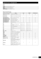
Midi Data Format, Synthesizer/sequencer Part - keyboard
 |
View all Yamaha MOXF8 manuals
Add to My Manuals
Save this manual to your list of manuals |
Page 119 highlights
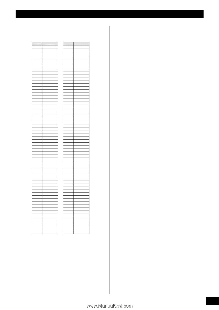
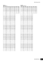
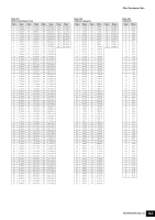
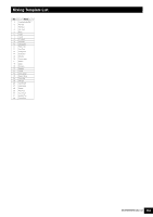
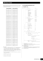
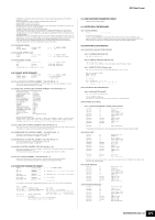
MIDI Data Format Many MIDI messages listed in the MIDI Data Format section are expressed in hexadecimal or binary numbers. Hexadecimal numbers may include the letter "H" as a suffix. The letter "n" indicates a certain whole number. The chart below lists the corresponding decimal number for each hexadecimal number. Decimal Hexadecimal 0 0 1 1 2 2 3 3 4 4 5 5 6 6 7 7 8 8 9 9 10 0A 11 0B 12 0C 13 0D 14 0E 15 0F 16 10 17 11 18 12 19 13 20 14 21 15 22 16 23 17 24 18 25 19 26 1A 27 1B 28 1C 29 1D 30 1E 31 1F 32 20 33 21 34 22 35 23 36 24 37 25 38 26 39 27 40 28 41 29 42 2A 43 2B 44 2C 45 2D 46 2E 47 2F 48 30 49 31 50 32 51 33 52 34 53 35 54 36 55 37 56 38 57 39 58 3A 59 3B 60 3C 61 3D 62 3E 63 3F Decimal Hexadecimal 64 40 65 41 66 42 67 43 68 44 69 45 70 46 71 47 72 48 73 49 74 4A 75 4B 76 4C 77 4D 78 4E 79 4F 80 50 81 51 82 52 83 53 84 54 85 55 86 56 87 57 88 58 89 59 90 5A 91 5B 92 5C 93 5D 94 5E 95 5F 96 60 97 61 98 62 99 63 100 64 101 65 102 66 103 67 104 68 105 69 106 6A 107 6B 108 6C 109 6D 110 6E 111 6F 112 70 113 71 114 72 115 73 116 74 117 75 118 76 119 77 120 78 121 79 122 7A 123 7B 124 7C 125 7D 126 7E 127 7F Additional Notes • For example, 144 - 159(Decimal)/9nH/1001 0000 - 1001 1111(Binary) indicate the note- on messages for the channels 1 through 16 respectively. 176 - 191/BnH/1011 0000 - 1011 1111 indicate the control change messages for the channels 1 through 16 respectively. 192 - 207/CnH/1100 0000 - 1100 1111 indicate the program change messages for the channels 1 through 16 respectively. 240/F0H/1111 0000 is positioned at the beginning of data to indicate a system exclusive message. 247/F7H/1111 0111 is positioned at the end of the system exclusive message. • aaH (Hexadecimal)/0aaaaaaa (Binary) indicates the data addresses. The data address consists of High, Mid and Low. • bbH/0bbbbbbb indicates byte counts. • ccH/0ccccccc indicates check sums. • ddH/0ddddddd indicates data/value. SYNTHESIZER/SEQUENCER PART (1) TRANSMIT FLOW MIDI
-
 1
1 -
2
-
3
-
4
-
5
-
6
-
7
-
8
-
9
-
10
-
11
-
12
-
13
-
14
-
15
-
16
-
17
-
18
-
19
-
20
-
21
-
22
-
23
-
24
-
25
-
26
-
27
-
28
-
29
-
30
-
31
-
32
-
33
-
34
-
35
-
36
-
37
-
38
-
39
-
40
-
41
-
42
-
43
-
44
-
45
-
46
-
47
-
48
-
49
-
50
-
51
-
52
-
53
-
54
-
55
-
56
-
57
-
58
-
59
-
60
-
61
-
62
-
63
-
64
-
65
-
66
-
67
-
68
-
69
-
70
-
71
-
72
-
73
-
74
-
75
-
76
-
77
-
78
-
79
-
80
-
81
-
82
-
83
-
84
-
85
-
86
-
87
-
88
-
89
-
90
-
91
-
92
-
93
-
94
-
95
-
96
-
97
-
98
-
99
-
100
-
101
-
102
-
103
-
104
-
105
-
106
-
107
-
108
-
109
-
110
-
111
-
112
-
113
-
 114
114 -
 115
115 -
 116
116 -
 117
117 -
 118
118 -
 119
119 -
 120
120 -
 121
121 -
 122
122 -
 123
123 -
 124
124 -
125
-
126
-
127
-
128
-
129
-
130
-
131
-
132
-
133
-
134
-
135
-
136
-
137
-
138
-
139
-
140
-
141
-
142
-
143
-
144
-
145
-
146
-
147
-
148
 |
 |