Yamaha SPS-900 SPS-900 ASSEMBLY INSTRUCTION - Page 2
Assembly - speaker stand
 |
View all Yamaha SPS-900 manuals
Add to My Manuals
Save this manual to your list of manuals |
Page 2 highlights
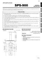
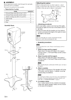
■ ASSEMBLY Before beginning assembly, check the parts list and make sure all the parts are included. You need a screwdriver for the assembly. • Parts list (for 2 units) NAME 1 Flat-head Phillips screws (M6 x 40 mm (1-9/16")) 2 Flat-head Phillips screws (M6 x 20 mm (13/16")) 3 Speaker mounting screws (M4 x 14 mm (9/16")) 4 Cable clamps 5 Spikes 6 Nuts QUANTITY 6 6 4 8 8 8 Assembly figure Example: Soavo-2 2 Plate Spacer Support 3 Base 4 Speaker cable 1 Attaching the spikes When setting up this unit on a thick carpet etc., attach spikes on the bottom side of the base in order to increase stability of this unit and to enhance sound quality. 1 2 6 5 Bottom side of the base • Attaching procedures 1.For each spike, screw a nut to the tip of the spike. 2.Screw the spike into the hole of the bottom side of the base. 3.Place the base with the topside up in the desired location and adjust the length of the spike to match the depth of the carpet. Note The tip of the spike may scratch or damage the flooring. Please be careful when positioning the stand. • Assembly procedures Note Do not overtighten the screws. Doing so may damage screws or screw holes. 1. Attach the base and the support. Align holes in the base with holes in the support, and then fasten 1 flat-head Phillips screws using a screwdriver. 2. Attach the plate and the support. Align holes in the plate with holes in the support, and then fasten 2 flat-head Phillips screws using a screwdriver. Note When attaching the plate, put the plate with the spacer-side up on the support. 3. Attach a speaker. Align holes on the bottom of the speaker with holes in the plate, and then fasten 3 speaker mounting screws using a screwdriver. Note The screw hole(s) which is (are) used varies (vary) depending on the speaker. For details about the screw hole(s) which is (are) used, refer to "USABLE SPEAKERS" on page 1. 4. Fix speaker cables. Put 4 cable clamps into the conduit to fix speaker cables after setting speaker cables into the conduit on the back of the support. 2 En
-
 1
1 -
 2
2
 |
 |
