| Section |
Page |
| 2001 Chevrolet Impala Owner's Manual |
1 |
|
24 |
| Here Are Questions Many People Ask About Safety Belts -- and the Answers |
25 |
| How to Wear Safety Belts Properly |
26 |
| Adults |
26 |
| Driver Position |
26 |
| Lap-Shoulder Belt |
26 |
| Shoulder Belt Height Adjuster |
28 |
| Safety Belt Use During Pregnancy |
33 |
| Right Front Passenger Position |
34 |
| Air Bag Systems |
35 |
| How the Air Bag Systems Work |
38 |
| Where are the air bags? |
38 |
| When should an air bag inflate? |
40 |
| What makes an air bag inflate? |
41 |
| How does an air bag restrain? |
41 |
| What will you see after an air bag inflates? |
41 |
| Servicing Your Air Bag-Equipped Vehicle |
43 |
| Center Front Passenger Position |
44 |
| Lap Belt |
44 |
| Rear Seat Passengers |
45 |
| Rear Seat Passenger Positions |
45 |
| Lap-Shoulder Belt |
45 |
| Rear Safety Belt Comfort Guides for Children and Small Adults |
49 |
| Children |
51 |
| Infants and Young Children |
51 |
| Restraint Systems for Children |
55 |
| Where to Put the Restraint |
58 |
| Top Strap |
59 |
| Securing a Child Restraint in a Rear Seat Position |
60 |
| Securing a Child Restraint in the Right Front Seat Position |
63 |
| Older Children |
67 |
| Safety Belt Extender |
70 |
| Checking Your Restraint Systems |
70 |
| Replacing Restraint System Parts After a Crash |
70 |
| Section 2 Features and Controls |
71 |
| Windows |
72 |
| Power Windows |
73 |
| Keys |
74 |
| Door Locks |
76 |
| Power Door Locks |
77 |
| Programmable Automatic Power Door Locks |
77 |
| Rear-Door Security Locks |
78 |
| Lockout Protection Feature |
78 |
| Leaving Your Vehicle |
78 |
| Remote Keyless Entry (If Equipped) |
79 |
| Operation |
80 |
| Panic Alarm Button |
80 |
| Transmitter Verification (If Equipped) |
80 |
| Illumination on Remote Activation |
81 |
| Matching Transmitter(s) to Your Vehicle |
81 |
| Battery Replacement |
81 |
| Resynchronization |
82 |
| Trunk |
83 |
| Trunk Lock |
83 |
| Remote Trunk Release |
83 |
| Trunk Assist Handle |
84 |
| Trunk Release Handle |
85 |
| Trap-Resistant Trunk Kit |
85 |
| Trunk Release Sensor Trap Alert System (If Equipped) |
86 |
| Disabling the Trunk Release Sensor |
87 |
| Servicing the Trunk Release Sensor |
87 |
| Theft |
88 |
| Key in the Ignition |
88 |
| Parking at Night |
88 |
| Parking Lots |
88 |
| Content Theft-Deterrent (Option) |
89 |
| Arming with the Power Lock Switch |
89 |
| Arming with the Remote Keyless Entry Transmitter |
90 |
| Disarming with the Remote Keyless Entry Transmitter |
90 |
| Disarming with Your Key |
90 |
| Vehicle Customization Settings |
90 |
| Passlock |
98 |
| New Vehicle Break-In |
99 |
| Ignition Positions |
99 |
| Retained Accessory Power (RAP) |
100 |
| Starting Your Engine |
100 |
| Starting Your 3400 V6 Engine |
101 |
| Starting Your 3800 Series II V6 Engine |
102 |
| Engine Coolant Heater (Option) |
103 |
| To Use the Engine Coolant Heater |
103 |
| Automatic Transaxle Operation |
104 |
| Parking Brake |
109 |
| Shifting Into PARK (P) |
110 |
| Column Shift |
110 |
| Console Shift |
111 |
| Leaving Your Vehicle With the Engine Running |
112 |
| Torque Lock |
112 |
| Shifting Out of PARK (P) |
113 |
| Parking Over Things That Burn |
113 |
| Engine Exhaust |
114 |
| Running Your Engine While You re Parked |
114 |
| Horn |
115 |
| Tilt Wheel |
115 |
| Turn Signal/Multifunction Lever |
116 |
| Turn Signal and Lane Change Indicator |
116 |
| Turn Signal On Chime |
117 |
| Headlamp High/Low-Beam Changer |
117 |
| Flash-to-Pass Feature |
117 |
| Windshield Wipers |
117 |
| Windshield Washer |
118 |
| Cruise Control (If Equipped) |
119 |
| Setting Cruise Control |
120 |
| Resuming a Set Speed |
121 |
| Increasing Speed While Using Cruise Control |
121 |
| Reducing Speed While Using Cruise Control |
121 |
| Passing Another Vehicle While Using Cruise Control |
121 |
| Using Cruise Control on Hills |
122 |
| Ending Cruise Control |
122 |
| Erasing Cruise Speed Memory |
122 |
| Exterior Lamps |
122 |
| Daytime Running Lamps / Automatic Headlamp Control |
123 |
| Delayed Headlamp Illumination |
124 |
| Fog Lamps (If Equipped) |
124 |
| Interior Lamps |
125 |
| Instrument Panel Brightness Control |
125 |
| Courtesy Lamps |
125 |
| Illuminated Entry (If Equipped) |
125 |
| Delayed Entry Lighting |
126 |
| Delayed Exit Lighting |
126 |
| Parade Mode |
126 |
| Rearview Mirror Reading Lamps |
126 |
| Reading Lamps (If Equipped) |
126 |
| Dome Lamp |
126 |
| Battery Rundown Protection |
127 |
| Mirrors |
127 |
| Inside Day/Night Rearview Mirror with Map Lamps |
127 |
| Inside Day/Night Rearview Mirror with OnStar and Map Lamps (Option) |
128 |
| Electrochromic Automatic Dimming Rearview Mirror (If Equipped) |
128 |
| Electrochromic Day/Night Rearview Mirror with OnStar and Map Lamps (Option) |
129 |
| Power Outside Mirrors |
130 |
| Convex Outside Mirror |
130 |
| Heated Outside Mirrors (If Equipped) |
130 |
| Storage Compartments |
131 |
| Glove Box |
131 |
| Front Armrest (If Equipped) |
131 |
| Center Console (If Equipped) |
131 |
| Rear Seat Armrest and Cupholder (If Equipped) |
131 |
| Trunk Convenience Net (If Equipped) |
131 |
| Ashtrays and Lighter |
131 |
| Sun Visors |
132 |
| Visor Vanity Mirrors |
132 |
| Accessory Power Outlet |
133 |
| Auxiliary Power Connection (Power Drop) |
134 |
| Cellular Phone Readiness Package (Option) |
134 |
| OnStar System (If Equipped) |
135 |
| Safety and Security Services |
136 |
| Premium Services (Includes Safety and Security Services) |
137 |
| OnStar System Limitations |
137 |
| Assist Handles |
137 |
| Garment Hooks |
137 |
| Power Sunroof (Option) |
138 |
| HomeLink Transmitter (Option) |
139 |
| Programming the HomeLink Transmitter |
140 |
| Operating the Transmitter |
141 |
| Training a Garage Opener with a Rolling Code Feature |
142 |
| Erasing Channels |
143 |
| Accessories |
143 |
| The Instrument Panel Your Information System |
144 |
| Instrument Panel Cluster |
146 |
| Speedometer and Odometer |
148 |
| Trip Odometer |
148 |
| Tachometer (If Equipped) |
148 |
| Warning Lights, Gages and Indicators |
149 |
| Safety Belt Reminder Light |
149 |
| Air Bag Readiness Light |
150 |
| Brake System Warning Light |
151 |
| Anti-Lock Brake System Warning Light (If Equipped) |
152 |
| Traction Control System Warning Light (3800 V6 Engine) |
152 |
| Engine Coolant Temperature Gage |
153 |
| Malfunction Indicator Lamp (Check Engine Light) |
154 |
| If the Light Is Flashing |
155 |
| If the Light Is On Steady |
155 |
| Emissions Inspection and Maintenance Programs |
156 |
| Low Oil Pressure Light |
157 |
| Cruise Light (If Equipped) |
157 |
| Fuel Gage |
158 |
| Message Center |
158 |
| Modes |
159 |
| Service Traction System (If Equipped) |
159 |
| Traction Active (If Equipped) |
159 |
| Battery Life Indicator |
160 |
| Hot Coolant Temp |
160 |
| Low Coolant Level |
161 |
| Low Oil Pressure |
161 |
| Low Eng Oil Level |
162 |
| Change Engine Oil |
162 |
| Door Ajar |
163 |
| Security |
163 |
| Low Brake Fluid |
164 |
| Low Fuel |
164 |
| Low Washer Fluid |
165 |
| Low Tire Pressure (If Equipped) |
165 |
| Service Vehicle Soon |
166 |
| Trunk Open |
166 |
| Highbeam Out |
167 |
| Driver Information Center (DIC) (Option) |
167 |
| Compass Variance |
169 |
| Setting the Variance |
169 |
| Automatic Compass Calibration |
169 |
| Manual Compass Calibration |
170 |
| Error Displays |
170 |
| Trip Computer |
170 |
| Resetting the Trip Computer |
170 |
| Section 3 Comfort Controls and Audio Systems |
171 |
| Comfort Controls |
172 |
| Manual Single Zone Climate Control |
172 |
| Fan Knob |
172 |
| Temperature Knob |
172 |
| Mode Knob |
172 |
| Dual ComforTemp Climate Control (If Equipped) |
174 |
| Fan Knob |
174 |
| Driver s Temperature Lever |
174 |
| Passenger s Temperature Lever |
174 |
| Mode Knob |
174 |
| Air Conditioning |
176 |
| Heating |
176 |
| Ventilation |
176 |
| Defogging and Defrosting |
176 |
| Rear Window Defogger |
177 |
| Ventilation System |
178 |
| Ventilation Tips |
178 |
| Audio Systems |
179 |
| Setting the Clock |
179 |
| Setting the Clock for Systems with Radio Data System |
179 |
| AM-FM Stereo |
180 |
| Playing the Radio |
180 |
| Finding a Station |
180 |
| Setting the Tone |
181 |
| Adjusting the Speakers |
182 |
| Radio Calibration |
182 |
| AM-FM Stereo with Cassette Tape Player with Radio Data System (RDS) and Automatic Tone Control (If Equipped) |
183 |
| Playing the Radio Finding a Station |
183 |
| Setting the Tone |
184 |
| Adjusting the Speakers |
185 |
| Using RDS |
186 |
| Playing a Cassette Tape |
189 |
| Tight/Loose Tape Sensor Defeat |
191 |
| CD Adapter Kits |
192 |
| AM-FM Stereo with Compact Disc Player with Radio Data System (RDS) and Automatic Tone Control (Option) |
192 |
| Playing the Radio |
192 |
| Finding a Station |
193 |
| Setting the Tone |
194 |
| Adjusting the Speakers |
195 |
| Using RDS |
196 |
| Playing a Compact Disc |
199 |
| AM-FM Stereo with Cassette Tape and Compact Disc Player with Radio Data System (RDS) and Automatic Tone Control (Option) |
201 |
| Playing the Radio |
201 |
| Finding a Station |
202 |
| Setting the Tone |
203 |
| Adjusting the Speakers |
204 |
| Using RDS |
204 |
| Playing a Cassette Tape |
207 |
| Tight/Loose Tape Sensor Defeat |
209 |
| Playing a Compact Disc |
209 |
| Theft-Deterrent Feature Non- RDS Radios |
211 |
| Theft-Deterrent Feature RDS Radios (If Equipped) |
211 |
| Audio Steering Wheel Controls (If Equipped) |
212 |
| Understanding Radio Reception |
213 |
| AM |
213 |
| FM Stereo |
213 |
| Tips About Your Audio System |
213 |
| Care of Your Cassette Tape Player |
214 |
| Care of Your Compact Discs |
215 |
| Care of Your Compact Disc Player |
215 |
| Backglass Antenna |
216 |
| Vehicle Customization Settings |
216 |
| Chime Level Adjustment |
216 |
| Section 4 Your Driving and the Road |
217 |
| Defensive Driving |
218 |
| Drunken Driving |
219 |
| Control of a Vehicle |
222 |
| Braking |
222 |
| Anti-Lock Brakes (If Equipped) |
223 |
| Using Anti- Lock |
225 |
| Braking in Emergencies |
225 |
| Traction Control System (3800 V6 Engine) |
225 |
| Steering |
227 |
| Power Steering |
227 |
| Steering Tips |
227 |
| Driving on Curves |
227 |
| Steering in Emergencies |
228 |
| Off-Road Recovery |
229 |
| Passing |
230 |
| Loss of Control |
231 |
| Skidding |
231 |
| Driving at Night |
232 |
| Driving in Rain and on Wet Roads |
234 |
| Hydroplaning |
235 |
| Driving Through Deep Standing Water |
236 |
| Driving Through Flowing Water |
236 |
| Some Other Rainy Weather Tips |
236 |
| City Driving |
237 |
| Freeway Driving |
238 |
| Before Leaving on a Long Trip |
239 |
| Highway Hypnosis |
240 |
| Hill and Mountain Roads |
240 |
| Winter Driving |
242 |
| Driving on Snow or Ice |
243 |
| If You re Caught in a Blizzard |
244 |
| Recreational Vehicle Towing |
246 |
| Loading Your Vehicle |
246 |
| Towing a Trailer |
248 |
| If You Do Decide To Pull A Trailer |
249 |
| Weight of the Trailer |
249 |
| Weight of the Trailer Tongue |
250 |
| Total Weight on Your Vehicle s Tires |
251 |
| Hitches |
251 |
| Safety Chains |
251 |
| Trailer Brakes |
251 |
| Driving with a Trailer |
252 |
| Following Distance |
252 |
| Passing |
252 |
| Backing Up |
252 |
| Making Turns |
253 |
| Turn Signals When Towing a Trailer |
253 |
| Driving On Grades |
253 |
| Parking on Hills |
254 |
| When You Are Ready to Leave After Parking on a Hill |
254 |
| Maintenance When Trailer Towing |
254 |
| Engine Cooling When Trailer Towing |
254 |
| Section 5 Problems on the Road |
255 |
| Hazard Warning Flashers |
256 |
| Other Warning Devices |
257 |
| Jump Starting |
257 |
| Towing Your Vehicle |
263 |
| Engine Overheating |
263 |
| Overheated Engine Protection Operating Mode |
263 |
| If Steam Is Coming From Your Engine |
264 |
| If No Steam Is Coming From Your Engine |
265 |
| Cooling System |
266 |
| How to Add Coolant to the Coolant Recovery Tank |
268 |
| How to Add Coolant to the Radiator |
270 |
| If a Tire Goes Flat |
275 |
| Changing a Flat Tire |
276 |
| Removing the Spare Tire and Tools |
277 |
| Removing the Flat Tire and Installing the Spare Tire |
279 |
| Storing the Flat Tire and Tools |
284 |
| Storing the Spare Tire and Tools |
285 |
| Compact Spare Tire |
286 |
| If You re Stuck: In Sand, Mud, Ice or Snow |
287 |
| Rocking Your Vehicle To Get It Out |
287 |
| Section 6 Service and Appearance Care |
288 |
| Service |
289 |
| Doing Your Own Service Work |
289 |
| Adding Equipment to the Outside of Your Vehicle |
290 |
| Fuel |
290 |
| Fuels in Foreign Countries |
292 |
| Filling Your Tank |
292 |
| Filling a Portable Fuel Container |
295 |
| Checking Things Under the Hood |
295 |
| Hood Release |
296 |
| Engine Compartment Overview |
297 |
| Engine Oil |
299 |
| Checking Engine Oil |
299 |
| When to Add Engine Oil |
300 |
| What Kind of Engine Oil to Use |
301 |
| Engine Oil Additives |
304 |
| When to Change Engine Oil |
304 |
| How to Reset the Change Engine Oil Message |
305 |
| What to Do with Used Oil |
305 |
| Engine Air Cleaner/Filter |
306 |
| Passenger Compartment Air Filter (If Equipped) |
307 |
| Automatic Transaxle Fluid |
308 |
| When to Check and Change |
308 |
| How to Check |
309 |
| Checking the Fluid Level |
309 |
| How to Add Fluid |
311 |
| Engine Coolant |
311 |
| What to Use |
312 |
| Checking Coolant |
313 |
| Adding Coolant |
314 |
| Radiator Pressure Cap |
315 |
| Power Steering Fluid |
315 |
| When to Check Power Steering Fluid |
315 |
| How to Check Power Steering Fluid |
316 |
| What to Use |
316 |
| Windshield Washer Fluid |
316 |
| What to Use |
316 |
| Adding Washer Fluid |
316 |
| Brakes |
318 |
| Brake Fluid |
318 |
| What to Add |
319 |
| Brake Wear |
320 |
| Brake Pedal Travel |
320 |
| Brake Adjustment |
320 |
| Replacing Brake System Parts |
321 |
| Battery |
321 |
| Vehicle Storage |
321 |
| Bulb Replacement |
322 |
| Halogen Bulbs |
322 |
| Headlamps, Front Parking and Turn Signal Lamps |
322 |
| Headlamp Aiming |
324 |
| Fog Lamps (If Equipped) |
324 |
| Tail/Stop/Turn Signal and Rear Sidemarker Lamps |
325 |
| Back-Up Lamp |
326 |
| Rear Courtesy Lamps |
326 |
| Windshield Wiper Blade Replacement |
327 |
| Tires |
328 |
| Inflation -- Tire Pressure |
329 |
| When to Check |
329 |
| How to Check |
329 |
| Tire Inflation Monitor System (If Equipped) |
330 |
| Tire Inspection and Rotation |
331 |
| When It s Time for New Tires |
333 |
| Buying New Tires |
333 |
| Uniform Tire Quality Grading |
334 |
| Treadwear |
335 |
| Traction AA, A, B, C |
335 |
| Temperature A, B, C |
335 |
| Wheel Alignment and Tire Balance |
336 |
| Wheel Replacement |
336 |
| Used Replacement Wheels |
337 |
| Tire Chains |
337 |
| Appearance Care |
338 |
| Cleaning the Inside of Your Vehicle |
338 |
| Cleaning of Fabric/Carpet |
338 |
| Using Multi-Purpose Interior Cleaner on Fabric |
339 |
| Special Fabric Cleaning Problems |
339 |
| Cleaning Vinyl |
340 |
| Cleaning Leather |
340 |
| Cleaning the Top of the Instrument Panel |
340 |
| Cleaning Interior Plastic Components |
340 |
| Care of Safety Belts |
340 |
| Cleaning Glass Surfaces |
341 |
| Cleaning the Outside of the Windshield and Wiper Blades |
341 |
| Weatherstrips |
341 |
| Cleaning the Outside of Your Vehicle |
342 |
| Washing Your Vehicle |
342 |
| Cleaning Exterior Lamps/Lenses |
342 |
| Finish Care |
342 |
| Cleaning Aluminum Wheels (If Equipped) |
343 |
| Cleaning Tires |
343 |
| Sheet Metal Damage |
343 |
| Finish Damage |
344 |
| Underbody Maintenance |
344 |
| Chemical Paint Spotting |
344 |
| GM Vehicle Care/Appearance Materials |
345 |
| Vehicle Identification Number (VIN) |
346 |
| Engine Identification |
346 |
| Service Parts Identification Label |
346 |
| Electrical System |
347 |
| Add-On Electrical Equipment |
347 |
| Headlamp Wiring |
347 |
| Windshield Wipers |
347 |
| Power Windows and Other Power Options |
347 |
| Fuses and Circuit Breakers |
348 |
| Driver s Side Instrument Panel Fuse Block |
348 |
| Passenger s Side Instrument Panel Fuse Block |
350 |
| Underhood Fuse Block (Upper) |
352 |
| Underhood Fuse Block (Lower) |
353 |
| Replacement Bulbs |
354 |
| Capacities and Specifications |
354 |
| Engine Specifications |
354 |
| Normal Maintenance Replacement Parts |
355 |
| Vehicle Dimensions |
355 |
| Section 7 Maintenance Schedule |
356 |
| Introduction |
357 |
| Your Vehicle and the Environment |
357 |
| Maintenance Requirements |
357 |
| How This Section is Organized |
358 |
| Part A: Scheduled Maintenance Services |
359 |
| Using Your Maintenance Schedule |
359 |
| Scheduled Maintenance |
360 |
| Footnotes |
360 |
| Scheduled Maintenance |
361 |
| Engine Oil Scheduled Maintenance |
361 |
| Scheduled Maintenance |
362 |
| Part B: Owner Checks and Services |
370 |
| At Each Fuel Fill |
370 |
| Engine Oil Level Check |
370 |
| Engine Coolant Level Check |
370 |
| Windshield Washer Fluid Level Check |
370 |
| At Least Once a Month |
370 |
| Tire Inflation Check |
370 |
| Cassette Deck Service |
370 |
| At Least Twice a Year |
371 |
| Restraint System Check |
371 |
| Wiper Blade Check |
371 |
| Trunk Release Sensor Check |
371 |
| Weatherstrip Lubrication |
371 |
| Automatic Transaxle Check |
371 |
| At Least Once a Year |
371 |
| Key Lock Cylinders Service |
371 |
| Body Lubrication Service |
371 |
| Starter Switch Check |
372 |
| Automatic Transaxle Shift Lock Control System Check |
372 |
| Ignition Transaxle Lock Check |
373 |
| Parking Brake and Automatic Transaxle PARK (P) Mechanism Check |
373 |
| Underbody Flushing Service |
373 |
| Part C: Periodic Maintenance Inspections |
374 |
| Steering, Suspension and Front Drive Axle Boot and Seal Inspection |
374 |
| Exhaust System Inspection |
374 |
| Engine Cooling System Inspection |
374 |
| Throttle System Inspection |
375 |
| Brake System Inspection |
375 |
| Part D: Recommended Fluids and Lubricants |
376 |
| Part E: Maintenance Record |
377 |
| Section 8 Customer Assistance Information |
380 |
| Customer Satisfaction Procedure |
381 |
| Customer Assistance for Text Telephone (TTY) Users |
383 |
| Customer Assistance Offices |
383 |
| United States |
383 |
| Canada |
384 |
| Mexico, Central America and Caribbean Islands/ Countries (Except Puerto Rico and U. S. Virgin Islands) |
384 |
| GM Mobility Program for Persons with Disabilities |
384 |
| Chevrolet Roadside Assistance Program |
385 |
| Canadian Roadside Assistance |
386 |
| Courtesy Transportation |
387 |
| Plan Ahead When Possible |
387 |
| Transportation Options |
387 |
| Shuttle Service |
387 |
| Public Transportation or Fuel Reimbursement |
387 |
| Courtesy Rental Vehicle |
388 |
| Additional Program Information |
388 |
| Warranty Information |
388 |
| REPORTING SAFETY DEFECTS TO THE UNITED STATES GOVERNMENT |
389 |
| REPORTING SAFETY DEFECTS TO THE CANADIAN GOVERNMENT |
389 |
 1
1 275
275 276
276 277
277 278
278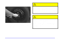 279
279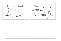 280
280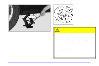 281
281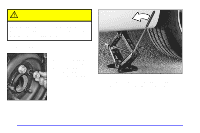 282
282 283
283 284
284 285
285