2012 Jeep Grand Cherokee User Guide - Page 132
2012 Jeep Grand Cherokee Manual

Page 132 highlights
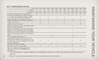
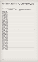
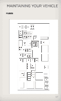
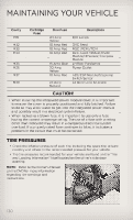
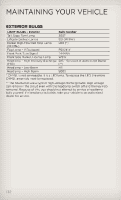
MAINTAINING YOUR VEHICLE Cavity M31 M32 M33 M34 Cartridge Fuse Mini Fuse 20 Amp Yellow 10 Amp Red 10 Amp Red 10 Amp Red Description B/U Lamps ORC Feed NGC (PCM)/TCM Park Assist Module/HVAC Module/IR Sensor/Compass Module LH Rear Parklamps Power Outlet ABS/ESP Module/Stoplamp Switch Sensor All Door Lock & Unlock M35 M36 M37 M38 15 Amp Blue 20 Amp Yellow 10 Amp Red 25 Amp Natural CAUTION! • When installing the integrated power module cover, it is important to ensure the cover is properly positioned and fully latched. Failure to do so may allow water to get into the integrated power module and possibly result in a electrical system failure. • When replacing a blown fuse, it is important to use only a fuse having the correct amperage rating. The use of a fuse with a rating other than indicated may result in a dangerous electrical system overload. If a properly rated fuse continues to blow, it indicates a problem in the circuit that must be corrected. TIRE PRESSURES • Check the inflation pressure of each tire, including the spare tire, at least monthly and inflate to the recommended pressure for your vehicle. • The tire pressures recommended for your vehicle are found on the "Tire and Loading Information" label located on the driver's side door opening. NOTE: Refer to the Owner's Manual on the DVD for more information regarding tire warnings and instructions. 130
-
 1
1 -
2
-
3
-
4
-
5
-
6
-
7
-
8
-
9
-
10
-
11
-
12
-
13
-
14
-
15
-
16
-
17
-
18
-
19
-
20
-
21
-
22
-
23
-
24
-
25
-
26
-
27
-
28
-
29
-
30
-
31
-
32
-
33
-
34
-
35
-
36
-
37
-
38
-
39
-
40
-
41
-
42
-
43
-
44
-
45
-
46
-
47
-
48
-
49
-
50
-
51
-
52
-
53
-
54
-
55
-
56
-
57
-
58
-
59
-
60
-
61
-
62
-
63
-
64
-
65
-
66
-
67
-
68
-
69
-
70
-
71
-
72
-
73
-
74
-
75
-
76
-
77
-
78
-
79
-
80
-
81
-
82
-
83
-
84
-
85
-
86
-
87
-
88
-
89
-
90
-
91
-
92
-
93
-
94
-
95
-
96
-
97
-
98
-
99
-
100
-
101
-
102
-
103
-
104
-
105
-
106
-
107
-
108
-
109
-
110
-
111
-
112
-
113
-
114
-
115
-
116
-
117
-
118
-
119
-
120
-
121
-
122
-
123
-
124
-
125
-
126
-
 127
127 -
 128
128 -
 129
129 -
 130
130 -
 131
131 -
 132
132 -
 133
133 -
 134
134 -
 135
135 -
 136
136 -
 137
137 -
138
-
139
-
140
-
141
-
142
-
143
-
144
-
145
-
146
-
147
-
148
 |
 |