2015 Kawasaki VERSYS 650 ABS Owners Manual - Page 74
2015 Kawasaki VERSYS 650 ABS Manual

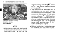
Page 74 highlights
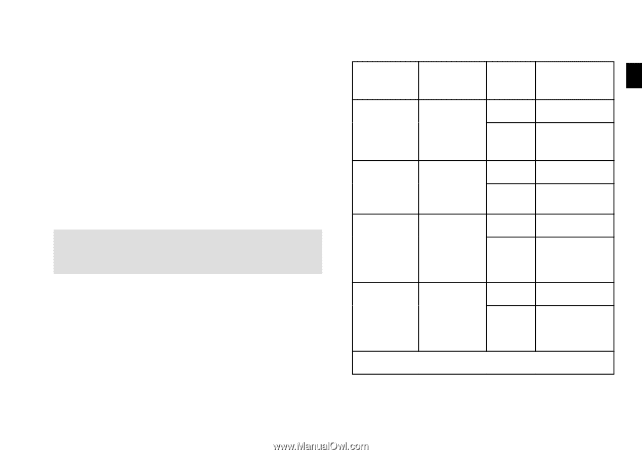
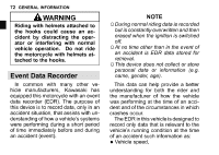
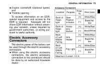
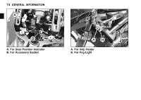
GENERAL INFORMATION 73 To access information on an EDR, special equipment and access to the EDR is required. Kawasaki will not share EDR information without obtaining your consent, unless required by government authorities, or acting pursuant to lawful authority. crankshaft rotational speed, • Engine and • Throttle opening. Accessory Connectors Location Back of Headlight Back of Headlight Back of Left Middle Fairing Back of Left Middle Fairing Purpose Gear Position Indicator Accessory Socket Grip Heater PolarWire Color ity White/Blue Black/Yellow White/Red Black/White White/Blue Black/Yellow White/Blue Black/Yellow Electric Accessory Connectors The electric power of the battery can be used through the electric accessory connectors. When using the electric accessory connectors, the electric accessory connection to the connectors should be done by an authorized Kawasaki dealer. • Fog Light (-) Maximum Current: 3.3 A
-
 1
1 -
2
-
3
-
4
-
5
-
6
-
7
-
8
-
9
-
10
-
11
-
12
-
13
-
14
-
15
-
16
-
17
-
18
-
19
-
20
-
21
-
22
-
23
-
24
-
25
-
26
-
27
-
28
-
29
-
30
-
31
-
32
-
33
-
34
-
35
-
36
-
37
-
38
-
39
-
40
-
41
-
42
-
43
-
44
-
45
-
46
-
47
-
48
-
49
-
50
-
51
-
52
-
53
-
54
-
55
-
56
-
57
-
58
-
59
-
60
-
61
-
62
-
63
-
64
-
65
-
66
-
67
-
68
-
 69
69 -
 70
70 -
 71
71 -
 72
72 -
 73
73 -
 74
74 -
 75
75 -
 76
76 -
 77
77 -
 78
78 -
 79
79 -
80
-
81
-
82
-
83
-
84
-
85
-
86
-
87
-
88
-
89
-
90
-
91
-
92
-
93
-
94
-
95
-
96
-
97
-
98
-
99
-
100
-
101
-
102
-
103
-
104
-
105
-
106
-
107
-
108
-
109
-
110
-
111
-
112
-
113
-
114
-
115
-
116
-
117
-
118
-
119
-
120
-
121
-
122
-
123
-
124
-
125
-
126
-
127
-
128
-
129
-
130
-
131
-
132
-
133
-
134
-
135
-
136
-
137
-
138
-
139
-
140
-
141
-
142
-
143
-
144
-
145
-
146
-
147
-
148
-
149
-
150
-
151
-
152
-
153
-
154
-
155
-
156
-
157
-
158
-
159
-
160
-
161
-
162
-
163
-
164
-
165
-
166
-
167
-
168
-
169
-
170
-
171
-
172
-
173
-
174
-
175
-
176
-
177
 |
 |