1998 Mercury Mountaineer Owner Guide 1st Printing - Page 142
1998 Mercury Mountaineer Manual
Page 142 highlights
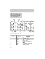
Roadside emergencies Always replace the cover to the Power Distribution Box before reconnecting the battery or refilling fluid reservoirs. 13 1 6 STARTER RELAY 1 A/C RELAY 2 7 14 10 6 2 15 3 8 2 HORN RELAY WIPER HI/LO RELAY 3 BLOWER MOTOR RELAY WASH PUMP RELAY FOG LAMP RELAY 9 5 7 11 3 1 4 9 WIPER PARK RELAY 12 8 The high-current fuses are coded as follows. Fuse/Relay Location 1 2 3 4 5 6 Fuse Amp Rating 50A** 40A** 50A** 20A** 50A** 20A** Description I/P Fuse Panel Blower Motor Relay 4 Wheel Anti-Lock Brake System (4WABS) Module Mainlight Switch, Instrument Cluster Ignition Switch, Starter Relay Transfer Case Relay 142 4 10 PCM POWER RELAY FUEL PUMP RELAY 5
-
 1
1 -
2
-
3
-
4
-
5
-
6
-
7
-
8
-
9
-
10
-
11
-
12
-
13
-
14
-
15
-
16
-
17
-
18
-
19
-
20
-
21
-
22
-
23
-
24
-
25
-
26
-
27
-
28
-
29
-
30
-
31
-
32
-
33
-
34
-
35
-
36
-
37
-
38
-
39
-
40
-
41
-
42
-
43
-
44
-
45
-
46
-
47
-
48
-
49
-
50
-
51
-
52
-
53
-
54
-
55
-
56
-
57
-
58
-
59
-
60
-
61
-
62
-
63
-
64
-
65
-
66
-
67
-
68
-
69
-
70
-
71
-
72
-
73
-
74
-
75
-
76
-
77
-
78
-
79
-
80
-
81
-
82
-
83
-
84
-
85
-
86
-
87
-
88
-
89
-
90
-
91
-
92
-
93
-
94
-
95
-
96
-
97
-
98
-
99
-
100
-
101
-
102
-
103
-
104
-
105
-
106
-
107
-
108
-
109
-
110
-
111
-
112
-
113
-
114
-
115
-
116
-
117
-
118
-
119
-
120
-
121
-
122
-
123
-
124
-
125
-
126
-
127
-
128
-
129
-
130
-
131
-
132
-
133
-
134
-
135
-
136
-
 137
137 -
 138
138 -
 139
139 -
 140
140 -
 141
141 -
 142
142 -
 143
143 -
 144
144 -
 145
145 -
 146
146 -
 147
147 -
148
-
149
-
150
-
151
-
152
-
153
-
154
-
155
-
156
-
157
-
158
-
159
-
160
-
161
-
162
-
163
-
164
-
165
-
166
-
167
-
168
-
169
-
170
-
171
-
172
-
173
-
174
-
175
-
176
-
177
-
178
-
179
-
180
-
181
-
182
-
183
-
184
-
185
-
186
-
187
-
188
-
189
-
190
-
191
-
192
-
193
-
194
-
195
-
196
-
197
-
198
-
199
-
200
-
201
-
202
-
203
-
204
-
205
-
206
-
207
-
208
-
209
-
210
-
211
-
212
-
213
-
214
-
215
-
216
 |
 |

Always replace the cover
to the Power Distribution
Box before reconnecting the
battery or refilling fluid
reservoirs.
The high-current fuses are coded
as follows.
Fuse/Relay
Location
Fuse Amp
Rating
Description
1
50A**
I/P Fuse Panel
2
40A**
Blower Motor Relay
3
50A**
4 Wheel Anti-Lock Brake System
(4WABS) Module
4
20A**
Mainlight Switch, Instrument
Cluster
5
50A**
Ignition Switch, Starter Relay
6
20A**
Transfer Case Relay
5
4
3
2
1
10
9
8
7
6
12
11
10
9
8
7
6
5
4
3
2
1
14
15
13
BLOWER
MOTOR
RELAY
STARTER
RELAY
FOG LAMP
RELAY
WASH PUMP
RELAY
HORN RELAY
FUEL PUMP
RELAY
PCM
POWER
RELAY
WIPER PARK
RELAY
WIPER HI/LO
RELAY
A/C RELAY
3
2
1
Roadside emergencies
142