2006 Yamaha Motorsports Grizzly 660 Auto. 4x4 SE Owners Manual - Page 20
2006 Yamaha Motorsports Grizzly 660 Auto. 4x4 SE Manual

Page 20 highlights
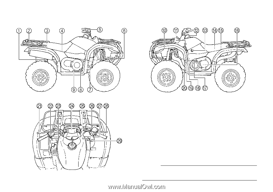
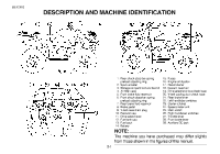
EBU00032 DESCRIPTION AND MACHINE IDENTIFICATION 1. Rear shock absorber spring preload adjusting ring 2. Spark arrester 3. Storage compartment and tool kit 4. Air filter case 5. Front brake fluid reservoir 6. Front shock absorber spring preload adjusting ring 7. Rear brake fluid reservoir 8. Brake pedal 9. V-belt case drain plug 10. Radiator cap 11. Drive select lever 12. Fuel tank cap 13. Fuel cock 14. Battery 15. 16. 17. 18. 19. 20. 21. 22. 23. 24. 25. 26. 27. 28. 29. Fuses Engine oil dipstick Recoil starter Coolant reservoir Drive select lever box check hose V-belt cooling duct check hose Rear brake lever Left handlebar switches Starter (choke) Speedometer unit Main switch Right handlebar switches Throttle lever Front brake lever Auxiliary DC jack NOTE: The machine you have purchased may differ slightly from those shown in the figures of this manual. 3-1
-
 1
1 -
2
-
3
-
4
-
5
-
6
-
7
-
8
-
9
-
10
-
11
-
12
-
13
-
14
-
 15
15 -
 16
16 -
 17
17 -
 18
18 -
 19
19 -
 20
20 -
 21
21 -
 22
22 -
 23
23 -
 24
24 -
 25
25 -
26
-
27
-
28
-
29
-
30
-
31
-
32
-
33
-
34
-
35
-
36
-
37
-
38
-
39
-
40
-
41
-
42
-
43
-
44
-
45
-
46
-
47
-
48
-
49
-
50
-
51
-
52
-
53
-
54
-
55
-
56
-
57
-
58
-
59
-
60
-
61
-
62
-
63
-
64
-
65
-
66
-
67
-
68
-
69
-
70
-
71
-
72
-
73
-
74
-
75
-
76
-
77
-
78
-
79
-
80
-
81
-
82
-
83
-
84
-
85
-
86
-
87
-
88
-
89
-
90
-
91
-
92
-
93
-
94
-
95
-
96
-
97
-
98
-
99
-
100
-
101
-
102
-
103
-
104
-
105
-
106
-
107
-
108
-
109
-
110
-
111
-
112
-
113
-
114
-
115
-
116
-
117
-
118
-
119
-
120
-
121
-
122
-
123
-
124
-
125
-
126
-
127
-
128
-
129
-
130
-
131
-
132
-
133
-
134
-
135
-
136
-
137
-
138
-
139
-
140
-
141
-
142
-
143
-
144
-
145
-
146
-
147
-
148
-
149
-
150
-
151
-
152
-
153
-
154
-
155
-
156
-
157
-
158
-
159
-
160
-
161
-
162
-
163
-
164
-
165
-
166
-
167
-
168
-
169
-
170
-
171
-
172
-
173
-
174
-
175
-
176
-
177
-
178
-
179
-
180
-
181
-
182
-
183
-
184
-
185
-
186
-
187
-
188
-
189
-
190
-
191
-
192
-
193
-
194
-
195
-
196
-
197
-
198
 |
 |