2010 Yamaha Motorsports Raider Owners Manual - Page 34
2010 Yamaha Motorsports Raider Manual

Page 34 highlights
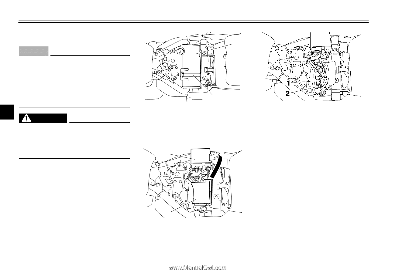
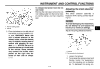
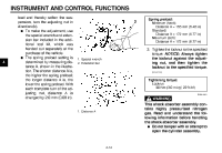
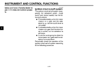
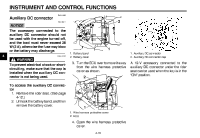
INSTRUMENT AND CONTROL FUNCTIONS EAU44585 Auxiliary DC connector ECA15311 2 NOTICE The accessory connected to the auxiliary DC connector should not be used with the engine turned off, and the load must never exceed 36 W (3 A), otherwise the fuse may blow or the battery may discharge. 4 WARNING To prevent electrical shock or shortcircuiting, make sure that the cap is installed when the auxiliary DC connector is not being used. To access the auxiliary DC connector 1. Remove the rider seat. (See page 4-12.) 2. Unhook the battery band, and then remove the battery cover. EWA12531 1 1. Battery band 2. Battery cover 1. Auxiliary DC connector 2. Auxiliary DC connector cap 3. Turn the ECU over to move it away from the wire harness protective cover as shown. 2 A 12-V accessory connected to the auxiliary DC connector under the rider seat can be used when the key is in the "ON" position. 1 1. Wire harness protective cover 2. ECU 4. Open the wire harness protective cover. 4-18
-
 1
1 -
2
-
3
-
4
-
5
-
6
-
7
-
8
-
9
-
10
-
11
-
12
-
13
-
14
-
15
-
16
-
17
-
18
-
19
-
20
-
21
-
22
-
23
-
24
-
25
-
26
-
27
-
28
-
 29
29 -
 30
30 -
 31
31 -
 32
32 -
 33
33 -
 34
34 -
 35
35 -
 36
36 -
 37
37 -
 38
38 -
 39
39 -
40
-
41
-
42
-
43
-
44
-
45
-
46
-
47
-
48
-
49
-
50
-
51
-
52
-
53
-
54
-
55
-
56
-
57
-
58
-
59
-
60
-
61
-
62
-
63
-
64
-
65
-
66
-
67
-
68
-
69
-
70
-
71
-
72
-
73
-
74
-
75
-
76
-
77
-
78
-
79
-
80
-
81
-
82
-
83
-
84
-
85
-
86
-
87
-
88
-
89
-
90
-
91
-
92
-
93
-
94
 |
 |