2010 Yamaha Motorsports V Star 1300 Tourer Owners Manual - Page 25
2010 Yamaha Motorsports V Star 1300 Tourer Manual

Page 25 highlights
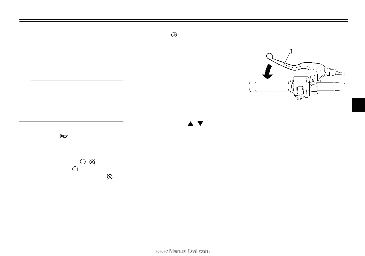
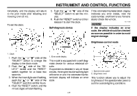
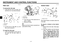
INSTRUMENT AND CONTROL FUNCTIONS has traveled both about 150 m (490 ft) and for approximately 15 seconds. However, the turn signal lights can also be canceled manually by pushing the switch in after it has returned to the center position. TIP The self-canceling system only operates when the vehicle is moving, so that the turn signal lights will not self-cancel while you are stopped at an intersection. EAU12500 EAU12711 EAU12820 Start switch " " Push this switch to crank the engine with the starter. See page 6-1 for starting instructions prior to starting the engine. EAU41700 Clutch lever The engine trouble warning light will come on when the key is turned to "ON" and the start switch is pushed, but this does not indicate a malfunction. 1. Clutch lever EAU42524 4 The clutch lever is located at the left handlebar grip. To disengage the clutch, pull the lever toward the handlebar grip. To engage the clutch, release the lever. The lever should be pulled rapidly and released slowly for smooth clutch operation. The clutch lever is equipped with a clutch switch, which is part of the ignition circuit cut-off system. (See page 4-17.) Horn switch " " Press this switch to sound the horn. EAU12660 Engine stop switch " / " Set this switch to " " before starting the engine. Set this switch to " " to stop the engine in case of an emergency, such as when the vehicle overturns or when the throttle cable is stuck. "SELECT" switch " / " This switch is used to perform selections in the odometer and tripmeters, to set the clock and to set the brightness control mode of the multi-function meter unit. See "Multi-function meter unit" on page 4-4 for detailed information. EAU42534 "RESET" switch This switch is used to perform selections in the tripmeters, to set the clock and to set the brightness control mode of the multi-function meter unit. See "Multi-function meter unit" on page 4-4 for detailed information. 4-8
-
 1
1 -
2
-
3
-
4
-
5
-
6
-
7
-
8
-
9
-
10
-
11
-
12
-
13
-
14
-
15
-
16
-
17
-
18
-
19
-
 20
20 -
 21
21 -
 22
22 -
 23
23 -
 24
24 -
 25
25 -
 26
26 -
 27
27 -
 28
28 -
 29
29 -
 30
30 -
31
-
32
-
33
-
34
-
35
-
36
-
37
-
38
-
39
-
40
-
41
-
42
-
43
-
44
-
45
-
46
-
47
-
48
-
49
-
50
-
51
-
52
-
53
-
54
-
55
-
56
-
57
-
58
-
59
-
60
-
61
-
62
-
63
-
64
-
65
-
66
-
67
-
68
-
69
-
70
-
71
-
72
-
73
-
74
-
75
-
76
-
77
-
78
-
79
-
80
-
81
-
82
-
83
-
84
-
85
-
86
-
87
-
88
-
89
-
90
-
91
-
92
-
93
-
94
-
95
-
96
-
97
-
98
-
99
-
100
-
101
-
102
 |
 |