3Com 3C16793 Installation Guide - Page 2
Connecting Workstations And Other Equipment To Your Switch - officeconnect
 |
UPC - 662705489445
View all 3Com 3C16793 manuals
Add to My Manuals
Save this manual to your list of manuals |
Page 2 highlights
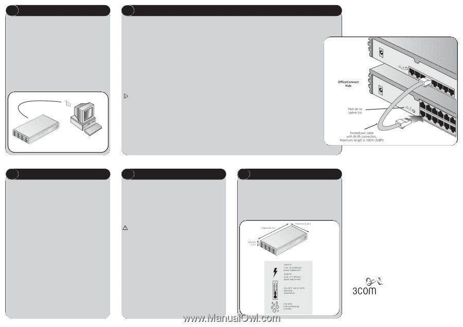
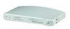
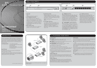
2 BEFORE YOU INSTALL YOUR SWITCH Unit Connections To connect OfficeConnect units (such as Hubs and other Switches) to your Switch, you need: ● One suitable Twisted Pair (TP) cable for each unit. Workstation Connections To connect workstations or other equipment (such as servers) directly to your Switch, you need: 1. One 10BASE-T, 100BASE-TX or 10/100BASE-TX adapter card for each workstation. 3Com produce a range of easy to install network adapters. 2. An operating system (for example, NetWare or Windows 95/98/Me/2000) with network support configured, running on your workstations. 3. One suitable Twisted Pair cable for each workstation. Figure 2 Workstation connections 1 3 2 3 CONNECTING WORKSTATIONS AND OTHER EQUIPMENT TO YOUR SWITCH Twisted Pair (TP) Cables Cables can be shielded (screened) or unshielded; 3Com recommends that you use shielded cable. Cables used for 100BASE-TX connections must be data grade (Category 5). The maximum length you can use is 100m (328ft). Twisted Pair (TP) cables are very easy to use. To connect a TP cable, simply slot the connector into the relevant RJ-45 port. When the connector is fully in, its latch locks it into place. To disconnect the cable, push the connector's latch in and remove it. When one end of a TP cable is connected to the Switch and the other end to the network interface card of a workstation the units will 'autonegotiate' to determine the fastest possible link speed between them. This may take a few seconds and the outcome will be reflected in the LEDs on the front of the Switch. The Switch detects all port connections, so you can start using your network immediately. If you need more ports, simply add another OfficeConnect unit. If the equipment connected to the Switch does not support autonegotiation or if it has been disabled, it must be configured to operate in half duplex mode Expanding Your Network You can increase the number of workstations that can connect to your network by adding OfficeConnect Hubs and Switches. You can connect either a 10BASE-T or a 100BASE-TX OfficeConnect unit to each port of the Switch. Use the following method for each unit: 1. Connect the Uplink/Normal port of the unit to any of the Switch's ports (as shown in Figure 3). If using the highest number port on the Switch (port 5 on Switch 5, port 8 on Switch 8), set its Uplink/Normal switch to Normal (out). OfficeConnect Switch 2. Set the Uplink/Normal switch on the other unit to Uplink (in). If you are connecting your switch to a unit with automatic MDI / MDIX functionality there is no need to follow the steps described above. The connection will happen automatically. Checking Unit Connections When you have connected all your units, power on the units and the Switch. The Port Status LEDs for the ports you have used on both the units and the Switch should be on. If they are not, check your connections and the settings of the Uplink/Normal switches. Spot Checks At frequent intervals, visually check that: ● Case vents are not obstructed. ● Cabling is secure and not pulled taut. Figure 3 Correct Connections for an OfficeConnect Switch 4 HOW YOUR SWITCH CAN BE USED Switchin Switching When a network of repeater hubs is in operation, any information that is sent by the workstations is passed around the whole network (regardless of the destination of the information). This can result in a lot of unnecessary traffic that can slow the network down. The Switch solves this problem because it 'listens' to the network and automatically learns what workstations can be reached through its ports. It can then selectively pass on any information by transmitting the traffic from the relevant port only (instead of all ports like a repeater hub). This operation is called 'switching'. The Switch effectively divides up your network, localizing the network traffic and passing on traffic as necessary. If you have workstations that communicate frequently in the same part of the network, traffic between them is not passed on unnecessarily to the remainder of the network, thereby reducing the load. If you have any high performance workstations that require a lot of bandwidth, connect them directly to the Switch. Connecting 10BASE-T and 100BASE-TX Networks The 10/100 ports can each be connected to either a 10BASE-T or 100BASE-TX network. If you have both types of network, you can join them together using the Switch allowing all your workstations to communicate. Alternatively, if you use 10BASE-T and want to improve network performance by introducing 100BASE-TX technology, the Switch protects the investment in your existing workstations because it maintains 10BASE-T connections to them. 5 PROBLEM SOLVING The Switch has been designed to aid you when detecting and solving possible problems with your network. These problems are rarely serious; the cause is usually a disconnected or damaged cable, or incorrect configuration. If this section does not solve your problem, contact your supplier for information on what to do next. Perform these actions first: ● Ensure all network equipment is powered on. ● Power each piece of network equipment off, wait about 5 seconds and then power each one on. CAUTION: Do not power the Switch off and on quickly. Wait about five seconds between power cycles. Check the following symptoms and solutions: Power LED not lit. Check your power adapter connection. If there is still no power, you may have a faulty power adapter which needs replacing with another OfficeConnect power adapter. Do not use any other power adapter with the Switch. Port Status LED not lit for a port that has a TP cable connected. After connection it may take several seconds for the port status LED's to illuminate. The port status LED should turn Green or Yellow for each port that is connected. Please refer to 'About Your Switch' for a full description of the LEDs. lf the Port Status LED has not lit after several seconds ensure the connected device is powered, the TP cable is not damaged and that it is correctly inserted at both ends. Also check whether the correct cable is being used (i.e. straightthrough or crossover), if the uplink port is being used, and whether the Uplink/Normal Switch is in the correct position. 6 DIMENSIONS AND STANDARDS Dimensions and Operating Conditions Standards Functional: Safety: ISO 8802/3 IEEE 802.3, 802.3u UL 1950, EN 60950 CSA 22.2 #950, IEC60950 EMC: Environmental: EN 55022 Class B EN 55024 FCC Part 15 Class B* ICES-003 Class B VCCI Class B CNS 13438 Class A EN 60068 (IEC 68) * Refer to Regulatory Notices section in the Support and Safety Information sheet Switch 5 480g (1.1 lb) Switch 8 535g (1.3 lb) 3Com Corporation, Corporate Headquarters, 5400 Bayfront Plaza, Santa Clara, CA 95052-8145 Copyright © 2001 3Com Corporation. All rights reserved. 3Com and OfficeConnect are registered trademarks of 3Com Corporation. The 3Com logo is a trademark of 3Com Corporation. Microsoft, MS-DOS, Windows and Windows NT are registered trademarks of Microsoft Corporation. Novell and NetWare are registered trademarks of Novell, Inc. All other company and product names may be trademarks of their respective companies
-
 1
1 -
 2
2
 |
 |