AIWA NSX-A505 Service Manual - Page 5
Regarding, reset, Confirmation, soldering, state, MICROCOMPUTER
 |
View all AIWA NSX-A505 manuals
Add to My Manuals
Save this manual to your list of manuals |
Page 5 highlights
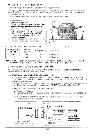
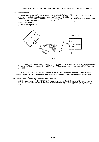
In such a cart, check also if the POWER AMPLIFIER circuit or power supply circuit has any abnormalities or not. 2-2. Regarding reset There arc cases that the machine does not work correctly because the MICROCOMPUTER is not reset even though the AC power cord is to• insetted, or the software reset (pressing the STOP key + POWER key) is performed. When the above described phenomenon occurs, it can leads to wrong judgment as if the MICROCOMPUTER is defective and to exchange the MICROCOMPUTER. In such a case, perform the forced-reset by the following procedure and check good or no good of the MICROCOMPUTER. O Remove the AC power cord. te et- 18 ' S, r 15 0 FRONT C.B 1.,.._.x FRONT C.B CI I3 VSS MICRO. COMPUTER VDD Short with tweezers. Fig-2-2 ® Short the both ends of the electrolytic capacitor Cl 13 that is connected to VDD of the MICROCOMPUTER with tweezers. ®, Connect the AC power cord again. If the MICROCOMPUTER returns to the normal operation, the MICROCOMPUTER is good. Note: The reference number or MICROCOMPUTER pin number of transistor (Q110) and electrolytic capacitor (C113) can change depending on the models. Be sure to check the reference numbers on schematic diagram before starting the discharging work. 2-3. Confirmation of soldering state of MICROCOMPUTER Check the soldering state of the MICROCOMPUTER in addition to the above described procedures. Be sure to exchange the MICROCOMPU1ER after surely confirming that the trouble is not caused by poor soldering but the MICROCOMPUTER itself. -5-
-
 1
1 -
 2
2 -
 3
3 -
 4
4 -
 5
5 -
 6
6 -
 7
7 -
 8
8 -
 9
9 -
 10
10 -
 11
11 -
12
-
13
-
14
-
15
-
16
-
17
-
18
-
19
-
20
-
21
-
22
-
23
-
24
-
25
-
26
-
27
-
28
-
29
-
30
-
31
-
32
-
33
-
34
-
35
-
36
-
37
-
38
-
39
-
40
-
41
-
42
-
43
-
44
-
45
 |
 |
