ASRock 2Core1333-2.66G User Manual
ASRock 2Core1333-2.66G Manual
 |
View all ASRock 2Core1333-2.66G manuals
Add to My Manuals
Save this manual to your list of manuals |
ASRock 2Core1333-2.66G manual content summary:
- ASRock 2Core1333-2.66G | User Manual - Page 1
2Core1333-2.66G User Manual Version 1.0 Published July 2007 Copyright©2007 ASRock INC. All rights reserved. 1 - ASRock 2Core1333-2.66G | User Manual - Page 2
any form or by any means, except duplication of documentation by the purchaser for backup purpose, without written consent of ASRock Inc. Products and corporate names appearing in this manual may or may not be registered trademarks or copyrights of their respective companies, and are used only for - ASRock 2Core1333-2.66G | User Manual - Page 3
17 2.7 Jumpers Setup 18 2.8 Onboard Headers and Connectors 19 2.9 SATAII Hard Disk Setup Guide 23 2.10 Serial ATA (SATA) / Serial ATAII (SATAII) Hard Disks Installation 24 2.11 Driver Installation Guide 24 2.12 HDMR Card and Driver Installation 24 2.13 Untied Overclocking Technology 24 3 BIOS - ASRock 2Core1333-2.66G | User Manual - Page 4
3.5 Boot Screen 39 3.5.1 Boot Settings Configuration 39 3.6 Security Screen 40 3.7 Exit Screen 41 4 Software Support 42 4.1 Install Operating System 42 4.2 Support CD Information 42 4.2.1 Running Support CD 42 4.2.2 Drivers Menu 42 4.2.3 Utilities Menu 42 4.2.4 Contact Information 42 4 - ASRock 2Core1333-2.66G | User Manual - Page 5
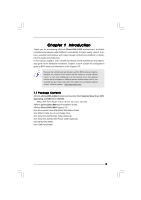
With Selected Dual Core CPU Operating at FSB1333 / 2.66GHz (Micro ATX Form Factor: 9.6-in x 9.0-in, 24.4 cm x 22.9 cm) ASRock 2Core1333-2.66G Quick Installation Guide ASRock 2Core1333-2.66G Support CD One 80-conductor Ultra ATA 66/100 IDE Ribbon Cable One Ribbon Cable for a 3.5-in Floppy Drive One - ASRock 2Core1333-2.66G | User Manual - Page 6
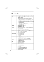
® ICH7 - Dual Channel DDRII Memory Technology (see CAUTION 3) - 2 x DDRII DIMM slots - Support DDRII667/533 (see CAUTION 4) - Max. capacity: 4GB (see CAUTION 5) - CPU Frequency Stepless Control (see CAUTION 6) - ASRock U-COP (see CAUTION 7) - Boot Failure Guard (B.F.G.) - 1 x PCI Express x16 slot - ASRock 2Core1333-2.66G | User Manual - Page 7
4 USB 2.0 ports) (see CAUTION 11) - 4Mb AMI BIOS - AMI Legal BIOS - Supports "Plug and Play" - ACPI 1.1 Compliance Wake Up Events - Supports jumperfree - AMBIOS 2.3.1 Support - Drivers, Utilities, AntiVirus Software (Trial Version) - CPU Temperature Sensing - Chassis Temperature Sensing - CPU - ASRock 2Core1333-2.66G | User Manual - Page 8
for details. 3. This motherboard supports Dual Channel Memory Technology. Before you implement Dual Channel Memory Technology, make sure to read the installation guide of memory modules on page ® Windows® VistaTM / VistaTM 64-bit driver and related information. ASRock website http://www - ASRock 2Core1333-2.66G | User Manual - Page 9
" option under BIOS. * If you plan to use external graphics card on this motherboard, please refer to Premium Discrete requirement at http://www.asrock.com * After June 1, 2007, all Windows® VistaTM systems are required to meet above minimum hardware requirements in order to qualify for Windows - ASRock 2Core1333-2.66G | User Manual - Page 10
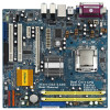
PCI2 7.1CH HD HDMR1 FLOPPY1 SATAII SATAII_3 SATAII_4 SATAII_1 1 USB4_5 1 USB6_7 SPEAKER1 1 USB2.0 CHA_FAN1 SATAII_2 PANEL 1 PLED PWRBTN 1 HDLED RESET 2Core1333-2.66G Dual Channel 21 20 19 18 17 16 1514 13 24.4cm (9.6 in) 7 8 9 10 11 12 1 PS2_USB_PWR1 Jumper 15 Chassis Speaker - ASRock 2Core1333-2.66G | User Manual - Page 11
1.5 HD 8CH I/O 1 2 3 6 4 7 5 8 13 12 11 10 9 1 Parallel Port 2 RJ-45 Port 3 Side Speaker (Gray) 4 Rear Speaker (Black) 5 Central / Bass (Orange) 6 Line In (Light Blue) *7 Front Speaker (Lime) 8 Microphone (Pink) 9 USB 2.0 Ports (USB01) 10 USB 2.0 Ports (USB23) 11 VGA Port 12 PS/2 - ASRock 2Core1333-2.66G | User Manual - Page 12
Chapter 2 Installation 2Core1333-2.66G is a Micro ATX form factor (9.6" x 9.0", 24.4 x 22.9 cm) motherboard. Before you install the motherboard, study the configuration of your chassis to ensure that the motherboard - ASRock 2Core1333-2.66G | User Manual - Page 13
on both sides of CPU socket on this motherboard. If the stickers are damaged, removed or bear the word "VOID", ASRock is not responsible for the after service of this CPU. ASRock CPU Sticker In the future, you may adopt other compatible Intel 775-LAND CPU on this motherboard. For the installation - ASRock 2Core1333-2.66G | User Manual - Page 14
Pick and Place Cap): Use your left hand index finger and thumb to support the load plate edge, engage PnP cap with right hand thumb and peel the PnP cap. 2. This cap must be placed if returning the motherboard for after service. Step 4. Close the socket: Step 4-1. Rotate the load plate onto the IHS. - ASRock 2Core1333-2.66G | User Manual - Page 15
Heatsink This motherboard is equipped with 775-Pin socket that supports Intel 775-LAND CPU. Please adopt the type of , see page 10, No. 3). For proper installation, please kindly refer to the instruction manuals of your CPU fan and heatsink. Below is an example to illustrate the installation of - ASRock 2Core1333-2.66G | User Manual - Page 16
2.5 Installation of Memory Modules (DIMM) 2Core1333-2.66G motherboard provides two 240-pin DDRII (Double Data Rate) DIMM slots, and supports Dual Channel Memory Technology. For dual channel configuration, you always need to install two identical (the same brand, speed, size and chip-type) memory - ASRock 2Core1333-2.66G | User Manual - Page 17
2.6 Expansion Slots (PCI, HDMR and PCI Express Slots) There are 2 PCI slots, 1 HDMR slot and 2 PCI Express slots on this motherboard. PCI slots: PCI slots are used to install expansion cards that have the 32-bit PCI interface. HDMR slot: HDMR slot is used to insert a HDMR card with v.92 Modem - ASRock 2Core1333-2.66G | User Manual - Page 18
2.7 Jumpers Setup The illustration shows how jumpers are setup. When the jumper cap is placed on pins, the jumper is "Short". If no jumper cap is placed on pins, the jumper is "Open". The illustration shows a 3-pin jumper whose pin1 and pin2 are "Short" when jumper cap is placed on these 2 - ASRock 2Core1333-2.66G | User Manual - Page 19
devices 80-conductor ATA 66/100 cable Note: Please refer to the instruction of your IDE device vendor for the details. Serial ATAII Connectors ( No. 11) SATAII_1 SATAII_4 SATAII_2 These Serial ATAII (SATAII) connectors support SATAII or SATA hard disk for internal storage devices. The current - ASRock 2Core1333-2.66G | User Manual - Page 20
allows convenient connection and control of audio devices. 1. High Definition Audio supports Jack Sensing, but the panel wire on the chassis must support HDA to function correctly. Please follow the instruction in our manual and chassis manual to install your system. 2. If you use AC'97 audio panel - ASRock 2Core1333-2.66G | User Manual - Page 21
connect a CPU fan cable to this connector and match the black wire to the ground pin. Though this motherboard provides 4-Pin CPU fan (Quiet Fan) support, the 3-Pin CPU fan still can work successfully even without the fan speed control function. If you plan to connect the 3-Pin CPU fan to - ASRock 2Core1333-2.66G | User Manual - Page 22
Serial port Header (9-pin COM1) (see p.10 No. 28) RRXD1 DDTR#1 DDSR#1 CCTS#1 1 RRI#1 RRTS#1 GND TTXD1 DDCD#1 This COM1 header supports a serial port module. 22 - ASRock 2Core1333-2.66G | User Manual - Page 23
guide. Some default setting of SATAII hard disks may not be at SATAII mode, which operate with the best performance. In order to enable SATAII function, please follow the below instruction 's website for details: http://www.hitachigst.com/hdd/support/download.htm The above examples are just for your - ASRock 2Core1333-2.66G | User Manual - Page 24
. STEP 4: Connect the other end of the SATA data cable to the SATA / SATAII hard disk. 2.11 Driver Installation Guide To install the drivers to your system, please insert the support CD to your optical drive first. Then, the drivers compatible to your system can be auto-detected and listed on the - ASRock 2Core1333-2.66G | User Manual - Page 25
Chapter 3 BIOS SETUP UTILITY 3.1 Introduction This section explains how to use the BIOS SETUP UTILITY to configure your system. The BIOS FWH chip on the motherboard stores the BIOS SETUP UTILITY. You may run the BIOS SETUP UTILITY when you start up the computer. Please press during the Power-On - ASRock 2Core1333-2.66G | User Manual - Page 26
Main Advanced BIOS SETUP UTILITY H/W Monitor Boot System Overview System Time System Date [14:00:09] [Fri 07/06/2007] BIOS Version : 2Core1333-2.66G L0.02 Processor Type : Dual Core CPU operating at FSB1333/2.66GHz (64bit) Processor Speed : 2666MHz Microcode Update : 6FD/A1 Cache Size - ASRock 2Core1333-2.66G | User Manual - Page 27
Main BIOS SETUP UTILITY Advanced H/W Monitor Boot Security Exit Advanced Settings WARNING : Setting wrong values in below sections may cause system to malfunction. CPU Configuration Chipset Configuration ACPI Configuration IDE Configuration PCIPnP Configuration Floppy Configuration SuperIO - ASRock 2Core1333-2.66G | User Manual - Page 28
(C1). The C1 state is supported through the native processor instructions HLT and MWAIT and requires no hardware support from the chipset. In the C1 overheated. This option will be hidden if the current CPU does not support CPU Thermal Throttling. No-Excute Memory Protection No-Execution (NX) Memory - ASRock 2Core1333-2.66G | User Manual - Page 29
Please note that enabling this function may reduce CPU voltage and lead to system stability or compatibility issue with some power supplies. Please set this item to [Disable] if above issue occurs. 3.3.2 Chipset Configuration BIOS SETUP UTILITY Advanced Chipset Configuration DRAM Frequency [ - ASRock 2Core1333-2.66G | User Manual - Page 30
DRAM RAS# Precharge This controls the idle clocks after a precharge command is issued. Configuration options: [2 DRAM Clocks], [3 DRAM Clocks], [4 DRAM Clocks], [5 DRAM Clocks], and [6 DRAM Clocks]. DRAM RAS# Activate to Precharge This controls the number of DRAM clocks for TRAS. Configuration - ASRock 2Core1333-2.66G | User Manual - Page 31
Front Panel Select [Auto], [Enabled] or [Disabled] for the onboard HD Audio Front Panel. CD-In Use this item to enable or disable CD-In of OnBoard HD Audio. If you plan to use this motherboard to submit Windows® VistaTM logo test, please disable this option. OnBoard Lan This allows you to enable or - ASRock 2Core1333-2.66G | User Manual - Page 32
field allows you to select whether to auto-detect or disable the Suspend-to-RAM feature. Select [Auto] will enable this feature if the system supports it. Restore on AC/Power Loss This allows you to set the power state after an unexpected AC/Power loss. If [Power Off] is selected - ASRock 2Core1333-2.66G | User Manual - Page 33
it is set to [IDE 1, SATA 2, SATA 4], then SATAII_1, SATAII_3 will not work. Because Intel® ICH7 south bridge only supports four IDE devices under legacy OS (Windows NT), you have to choose [SATA 1, SATA 2, SATA 3, SATA 4], [SATA "Primary IDE Master" as the example in the following instruction. 33 - ASRock 2Core1333-2.66G | User Manual - Page 34
Large Mode Block (Multi-Sector Transfer) PIO Mode DMA Mode S.M.A.R.T. 32Bit Data Transfer :Hard Disk :ST340014A :40.0 GB :Supported :16Sectors :4 :MultiWord DMA-2 :Ultra DMA-5 :Supported [Auto] [Auto] [Auto] [Auto] [Auto] [Disabled] [Enabled] Select the type of device connected to the system. +F1 - ASRock 2Core1333-2.66G | User Manual - Page 35
S.M.A.R.T. Use this item to enable or disable the S.M.A.R.T. (Self-Monitoring, Analysis, and Reporting Technology) feature. Configuration options: [Disabled], [Auto], [Enabled]. 32-Bit Data Transfer Use this item to enable 32-bit access to maximize the IDE hard disk data transfer rate. 3.3.5 PCIPnP - ASRock 2Core1333-2.66G | User Manual - Page 36
3.3.6 Floppy Configuration In this section, you may configure the type of your floppy drive. BIOS SETUP UTILITY Advanced Floppy Configuration Floppy A [1.44 MB 312"] Select the type of floppy drive connected to the system. +F1 F9 F10 ESC Select Screen Select Item Change Option General Help - ASRock 2Core1333-2.66G | User Manual - Page 37
parallel port. Configuration options: [IRQ5] and [IRQ7]. 3.3.8 USB Configuration BIOS SETUP UTILITY Advanced USB Configuration USB Controller USB 2.0 Support Legacy USB Support [Enabled] [Enabled] [Disabled] To enable or disable the onboard USB controllers. +F1 F9 F10 ESC Select Screen Select - ASRock 2Core1333-2.66G | User Manual - Page 38
3.4 Hardware Health Event Monitoring Screen In this section, it allows you to monitor the status of the hardware on your system, including the parameters of the CPU temperature, motherboard temperature, CPU fan speed, chassis fan speed, and the critical voltage. BIOS SETUP UTILITY Main Advanced - ASRock 2Core1333-2.66G | User Manual - Page 39
3.5 Boot Screen In this section, it will display the available devices on your system for you to configure the boot settings and the boot priority. Main Advanced BIOS SETUP UTILITY H/W Monitor Boot Security Exit Boot Settings Boot Settings Configuration Configure Settings during System Boot. - ASRock 2Core1333-2.66G | User Manual - Page 40
3.6 Security Screen In this section, you may set or change the supervisor/user password for the system. For the user password, you may also clear it. BIOS SETUP UTILITY Main Advanced H/W Monitor Boot Security Exit Security Settings Supervisor Password : Not Installed User Password : Not - ASRock 2Core1333-2.66G | User Manual - Page 41
3.7 Exit Screen Main BIOS SETUP UTILITY Advanced H/W Monitro Boot Security Exit Exit Options Save Changes and Exit Discard Changes and Exit Discard Changes Load Optimal Defaults Exit system setup after saving the changes. F10 key can be used for this operation. Select Screen Select Item - ASRock 2Core1333-2.66G | User Manual - Page 42
applications software that the motherboard supports. Click on a specific item then follow the installation wizard to install it. 4.2.4 Contact Information If you need to contact ASRock or want to know more about ASRock, welcome to visit ASRock's website at http://www.asrock.com; or you may contact
-
 1
1 -
 2
2 -
 3
3 -
 4
4 -
 5
5 -
 6
6 -
 7
7 -
8
-
9
-
10
-
11
-
12
-
13
-
14
-
15
-
16
-
17
-
18
-
19
-
20
-
21
-
22
-
23
-
24
-
25
-
26
-
27
-
28
-
29
-
30
-
31
-
32
-
33
-
34
-
35
-
36
-
37
-
38
-
39
-
40
-
41
-
42
 |
 |

1
2Core1333-2.66G
User Manual
Version 1.0
Published July 2007
Copyright©2007 ASRock INC. All rights reserved.