ASRock 4Core1333-FullHD User Manual - Page 27
Front Panel Audio Header
 |
View all ASRock 4Core1333-FullHD manuals
Add to My Manuals
Save this manual to your list of manuals |
Page 27 highlights
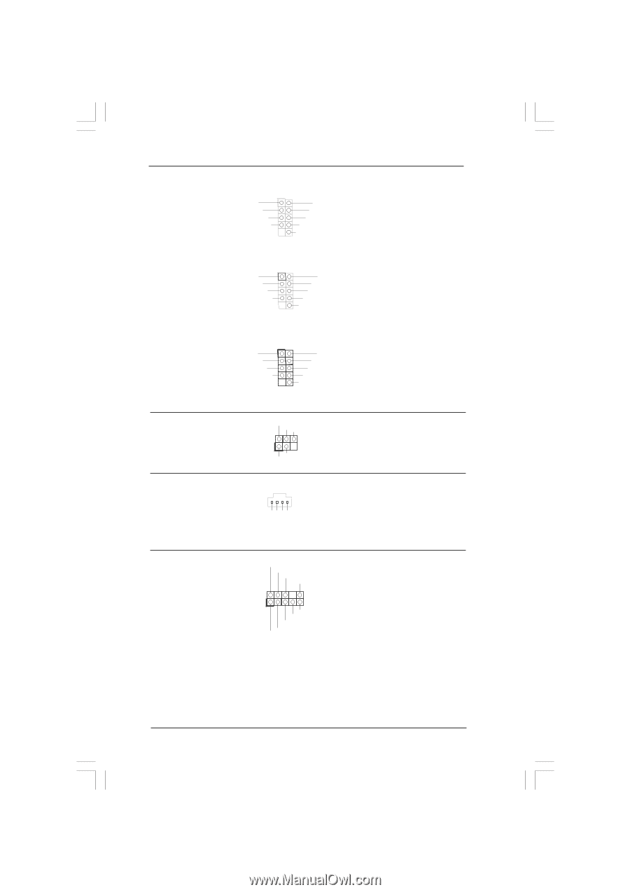
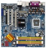
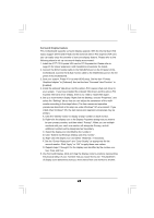
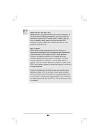
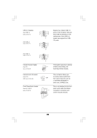
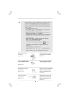
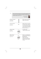
USB 2.0 Headers (9-pin USB8_9) (see p.12 No. 12) (9-pin USB6_7) (see p.12 No. 11) USB_PWR P-9 P+9 GND DUMMY 1 GND P+8 P-8 USB_PWR Besides four default USB 2.0 ports on the I/O panel, there are three USB 2.0 headers on this motherboard. Each USB 2.0 header can support two USB 2.0 ports. USB_PWR P-7 P+7 GND DUMMY 1 GND P+6 P-6 USB_PWR USB_PWR P-5 P+5 GND DUMMY 1 GND P+4 P-4 USB_PWR (9-pin USB4_5) (see p.12 No. 13) Infrared Module Header (5-pin IR1) (see p.12, No. 24) Internal Audio Connector (4-pin CD1) (CD1: see p.12, No. 29) IRTX +5VSB DUMMY 1 GND IRRX CD1 CD-L GND GND CD-R Front Panel Audio Header (9-pin HD_AUDIO1) (see p.12, No. 28) GND PRESENCE# MIC_RET OUT_RET 1 OUT2_L J_SENSE OUT2_R MIC2_R MIC2_L This header supports an optional wireless transmitting and receiving infrared module. This connector allows you to receive stereo audio input from sound sources such as a CD-ROM, DVD-ROM, TV tuner card, or MPEG card. This is an interface for the front panel audio cable that allows convenient connection and control of audio devices. 27
-
 1
1 -
2
-
3
-
4
-
5
-
6
-
7
-
8
-
9
-
10
-
11
-
12
-
13
-
14
-
15
-
16
-
17
-
18
-
19
-
20
-
21
-
 22
22 -
 23
23 -
 24
24 -
 25
25 -
 26
26 -
 27
27 -
 28
28 -
 29
29 -
 30
30 -
 31
31 -
 32
32 -
33
-
34
-
35
-
36
-
37
-
38
-
39
-
40
-
41
-
42
-
43
-
44
-
45
-
46
-
47
-
48
-
49
-
50
-
51
-
52
-
53
-
54
-
55
-
56
-
57
-
58
 |
 |