ASRock 770DE3L Quick Installation Guide - Page 21
Chassis and Power Fan Connectors - cpu support
 |
View all ASRock 770DE3L manuals
Add to My Manuals
Save this manual to your list of manuals |
Page 21 highlights
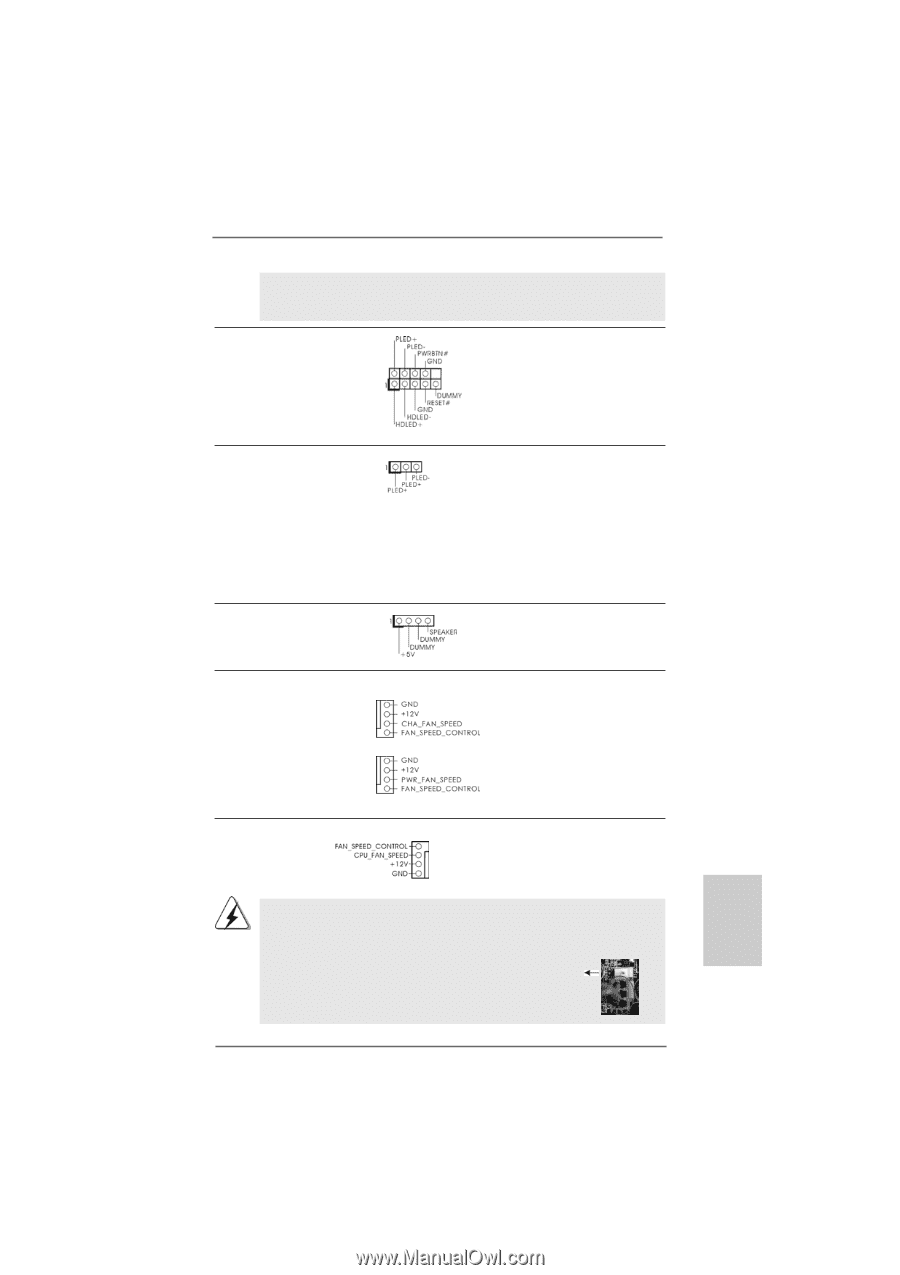
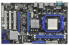
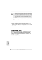
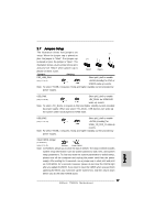
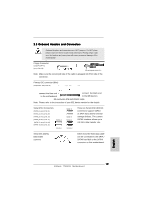
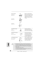
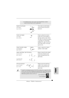
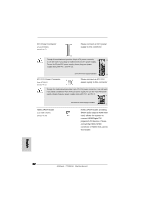
D. MIC_RET and OUT_RET are for HD audio panel only. You don't need to connect them for AC'97 audio panel. System Panel Header (9-pin PANEL1) (see p.2 No. 26) This header accommodates several system front panel functions. Power LED Header (3-pin PLED1) (see p.2 No. 29) Chassis Speaker Header (4-pin SPEAKER 1) (see p.2 No. 27) Chassis and Power Fan Connectors (4-pin CHA_FAN1) (see p.2 No. 13) (4-pin PWR_FAN1) (see p.2 No. 38) Please connect the chassis power LED to this header to indicate system power status. The LED is on when the system is operating. The LED keeps blinking in S1 state. The LED is off in S3/S4 state or S5 state (power off). Please connect the chassis speaker to this header. Please connect the fan cables to the fan connectors and match the black wire to the ground pin. CPU Fan Connector (4-pin CPU_FAN1) (see p.2 No. 5) Please connect the CPU fan 4 cable to this connector and 3 2 match the black wire to the 1 ground pin. Though this motherboard provides 4-Pin CPU fan (Quiet Fan) support, the 3-Pin CPU fan still can work successfully even without the fan speed control function. If you plan to connect the 3-Pin CPU fan to the CPU fan connector on this motherboard, please connect it to Pin 1-3. Pin 1-3 Connected 3-Pin Fan Installation 21 ASRock 770DE3L Motherboard English
-
 1
1 -
2
-
3
-
4
-
5
-
6
-
7
-
8
-
9
-
10
-
11
-
12
-
13
-
14
-
15
-
 16
16 -
 17
17 -
 18
18 -
 19
19 -
 20
20 -
 21
21 -
 22
22 -
 23
23 -
 24
24 -
 25
25 -
 26
26 -
27
-
28
-
29
-
30
-
31
-
32
-
33
-
34
-
35
-
36
-
37
-
38
 |
 |